Image processing device, image processing method, and imaging device

Active Publication Date: 2016-09-08
SONY CORP
View PDF6 Cites 21 Cited by
  • Summary
  • Abstract
  • Description
  • Claims
  • Application Information

AI Technical Summary

Benefits of technology

[0019]According to the present technology, a depth map is generated through a matching process using a first image generated by a first imaging unit which has a pixel configuration including pixels having different polarization directions and a second image generated by a second imaging unit which has a different pixel configuration from the pixel configuration of the first imaging unit. A normal-line map is generated based on a polarization state of a polari

Problems solved by technology

The active schemes are, for example, schemes of irradiating subjects with light and acquiring 3-dimensional shapes based on reflected light from the subjects and are not simple schemes in terms

Method used


Image

  • Image processing device, image processing method, and imaging device
  • Image processing device, image processing method, and imaging device
  • Image processing device, image processing method, and imaging device

Examples


first embodiment

2-1. Configuration and Operation in First Embodiment

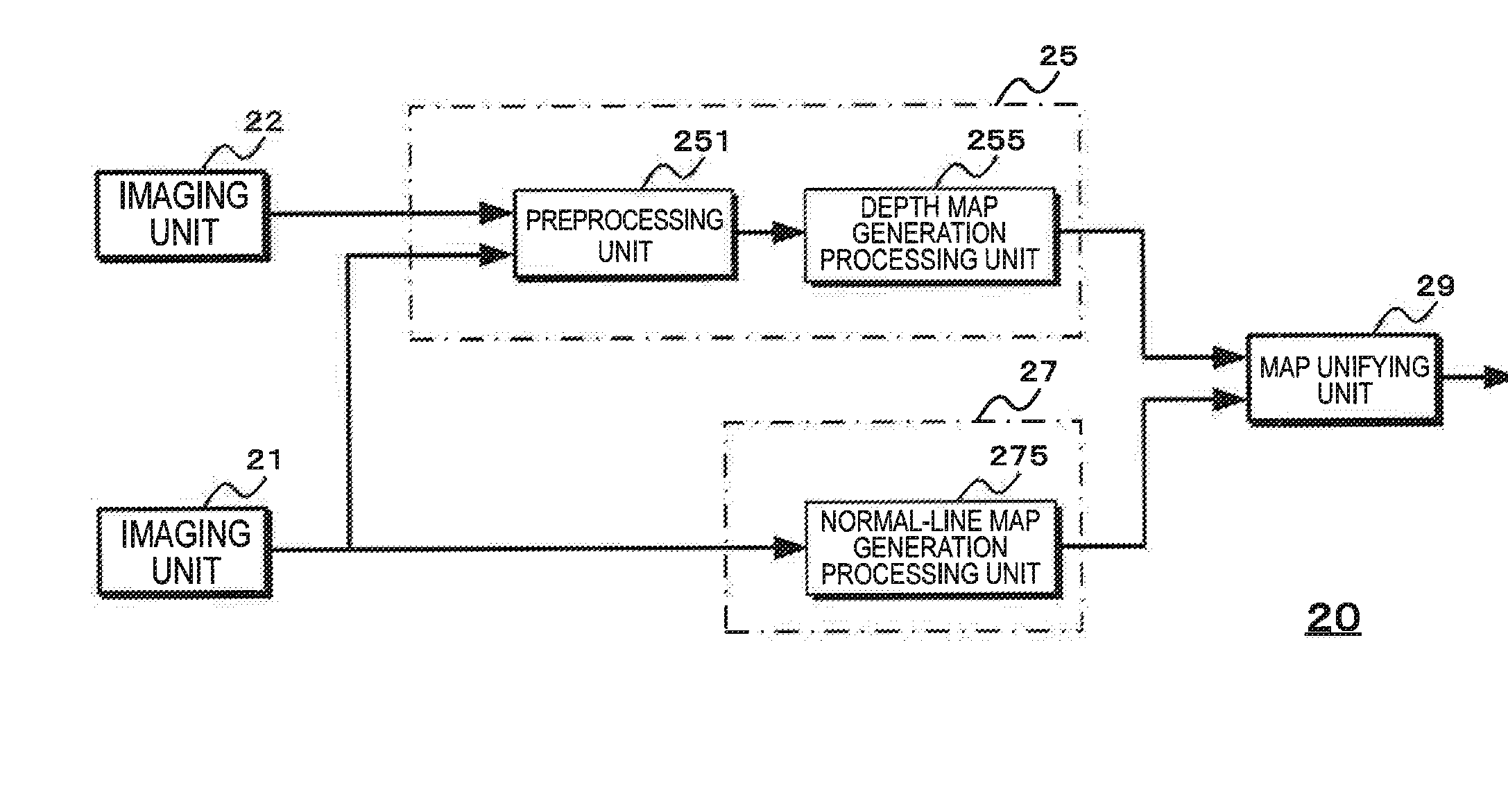
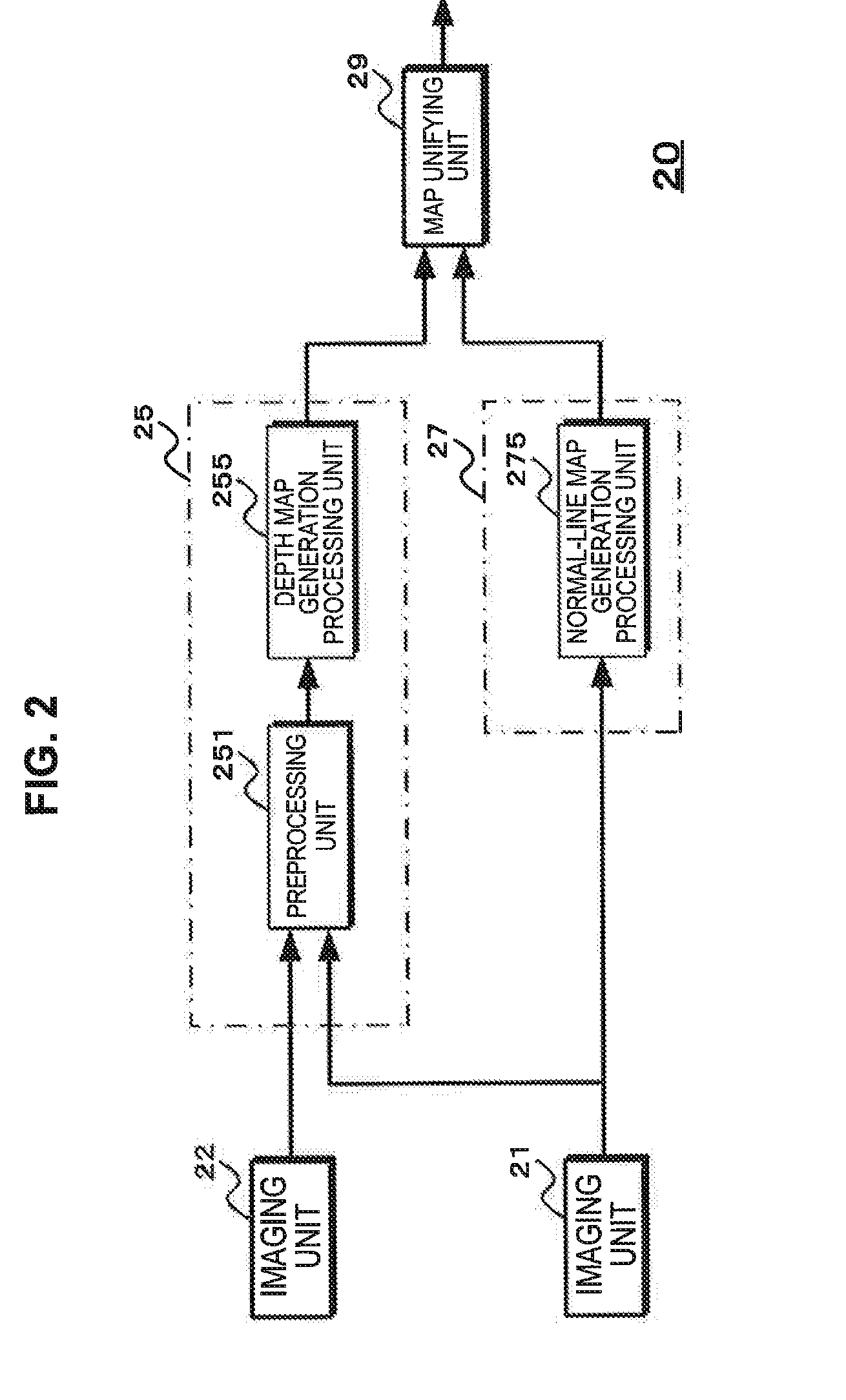
[0062]FIG. 2 exemplifies a configuration according to a first embodiment. An image processing device 20 includes imaging units 21 and 22, a depth map generation unit 25, a normal-line map generation unit 27, and a map unifying unit 29. The imaging units 21 and 22 correspond to stereo cameras and may be provided separately from the image processing device 20.

[0063]The imaging unit 21 corresponds to the first imaging unit which has a pixel configuration including pixels with different polarization characteristics. The imaging unit 22 corresponds to the second imaging unit which has a pixel configuration with no polarization characteristics.

[0064]FIG. 3 exemplifies a pixel configuration of an image sensor included in an imaging unit. FIG. 3 illustrates a part of the image sensor. FIG. 3(A) illustrates the pixel configuration of an image sensor 210 included in the imaging unit 21 and FIG. 3(B) illustrates the pixel configuration of an ...

second embodiment

3-1. Configuration and Operation in Second Embodiment

[0115]FIG. 16 is a diagram exemplifying a configuration according to the second embodiment. An image processing device 30 includes imaging units 31 and 32, a depth map generation unit 35, a normal-line map generation unit 37, and a map unifying unit 39. The imaging units 31 and 32 correspond to stereo cameras and may be provided separately from the image processing device 30.

[0116]The imaging unit 31 corresponds to a first imaging unit which has a pixel configuration including the first pixel group formed by the pixels with polarization characteristics and the second pixel group formed by the pixels having the different polarization direction from the polarization direction of the first pixel group or the pixels with no polarization characteristics. The imaging unit 32 corresponds to a second imaging unit which has a pixel configuration including the third pixel group formed by the pixels having the different polarization directio...

first modification example

3-2. First Modification Example of Second Embodiment

[0140]In the above-described embodiment, the configuration in which the image sensor configured with the pixels of the single color is used in the imaging units 31 and 32 has been exemplified, but a configuration in which an image sensor configured to include pixels of a plurality of colors may be used. Next, a case in which an image sensor including red, blue, and green pixels formed in a Bayer array is used in the imaging units 31 and 32 will be described according to a second modification example of the second embodiment. The configuration of the image processing device is assumed to have the same configuration as that of FIG. 16.

[0141]FIG. 23 exemplifies a pixel configuration of an image sensor included in an imaging unit according to a first modification example. FIG. 23 illustrates a part of the image sensor. FIG. 23(A) illustrates the pixel configuration of an image sensor 311 included in the imaging unit 31 and FIG. 23 (B) ...


PUM


Abstract

A depth map generation unit (15) generates a depth map through a matching process using a first image generated by a first imaging unit which has a pixel configuration including pixels having different polarization directions and a second image generated by a second imaging unit which has a different pixel configuration from the pixel configuration of the first imaging unit. A normal-line map generation unit (17) generates a normal-line map based on a polarization state of a polarized image of at least one of the first and second images. A map unifying unit (19) performs a process of unifying the generated depth map and the generated normal-line map and acquires an image in which the number of pixels is not reduced while generating the depth map with precision equal to or greater than the generated depth map. The image in which the number of pixels is not reduced can be acquired while generating the highly precise depth map.

Description

TECHNICAL FIELD[0001]The present disclosure relates to an image processing device, an image processing method, and an imaging device configured to acquire an image of which the number of pixels is not reduced while generating a highly precise depth map.BACKGROUND ART[0002]In recent years, means for simply acquiring 3-dimensional shapes has been requested along with lower priced 3D printers.[0003]As means for acquiring the 3-dimensional shapes of subjects, there are active and passive schemes. The active schemes are, for example, schemes of irradiating subjects with light and acquiring 3-dimensional shapes based on reflected light from the subjects and are not simple schemes in terms of power consumption, component cost, or the like. In contrast to the active schemes, the passive schemes are schemes of acquiring 3-dimensional shapes without irradiating subjects with light and are simpler schemes than the active schemes. As the passive methods, for example, a scheme of generating a de...

Claims


Application Information

Patent Timeline
IPC IPC(8): H04N13/02H04N13/00G06K9/62G01B11/24G01C3/08
CPCH04N13/0271G01B11/24G01C3/08H04N2013/0081G06K9/6202H04N13/0022H04N13/025G01C11/30G06T7/55H04N13/239H04N13/128H04N13/25H04N13/271
Inventor HIRASAWA, YASUTAKA
Owner SONY CORP
Why Eureka
Try Eureka