Cosmetic applicator with rotary cartridge

a technology of cosmetic applicators and rotary cartridges, which is applied in the direction of packaging foodstuffs, packaging goods, transportation and packaging, etc., can solve the problems of spreading too much cosmetic liquid to the user's face, and achieve the effects of reducing avoiding the possibility of shaking or shifting, and avoiding shaking or shifting

Active Publication Date: 2018-06-28
MEI SHUAL COSMETICS
View PDF2 Cites 3 Cited by
  • Summary
  • Abstract
  • Description
  • Claims
  • Application Information

AI Technical Summary

Benefits of technology

[0018]The present invention has advantages which are that the clip is connected to the groove between the case and the body before first use. The clip performs a safety device and prevents the user to unintentionally rotate or push the cosmetic applicator. The clip eliminates the shortcomings of the conventional cosmetic applicator mentioned above.
[0019]When first time using the cosmetic applicator of the present invention, the clip is removed from the groove, and the rotary member is rotated relative to the threaded portion to move the case from the initial position to the open position. The contact member presses the liquid tube so that the liquid tube and the duct move toward the tip part. In the same time, the sealing member moves in the passage. The distance between the contact portion and the shoulder is larger than the distance that the sealing member is removed from the passage so that the sealing member is removed from the passage. The user then shakes the cosmetic applicator of the present invention and the sealing member does not seal the guide tube, and the rod and the sealing member stir the cosmetic liquid, so that the cosmetic liquid in the liquid tube flows through the gap between the sealing member and the duct and flows to the tip part via the guide tube. The cosmetic liquid is evenly output from the tip part.
[0020]The contact member is a T-shaped member, so that the liquid tube can be firmly pushed to contact the recess to reduce the possibility of shaking or shifting. Therefore, the liquid tube is positioned stably and the rotation of the case is smooth and reliable.

Problems solved by technology

However, the button often pushed unintentionally so that the cosmetic liquid is squeezed at a large amount and absorbed in the tip part, and this may spread too much cosmetic liquid to the user's face and which is not a desired situation for the user.

Method used


Image

  • Cosmetic applicator with rotary cartridge
  • Cosmetic applicator with rotary cartridge
  • Cosmetic applicator with rotary cartridge

Examples


Embodiment Construction

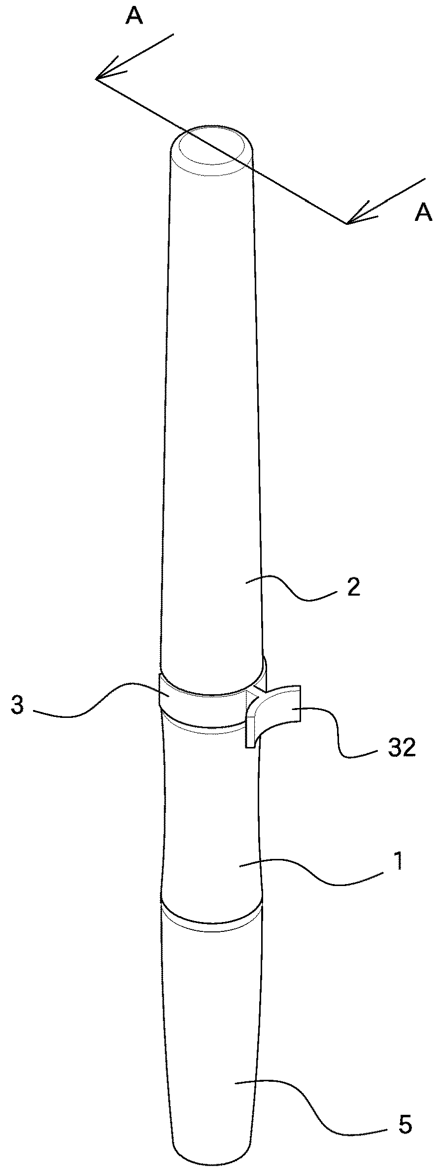
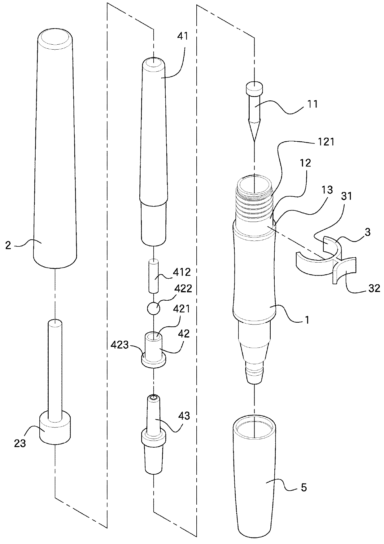
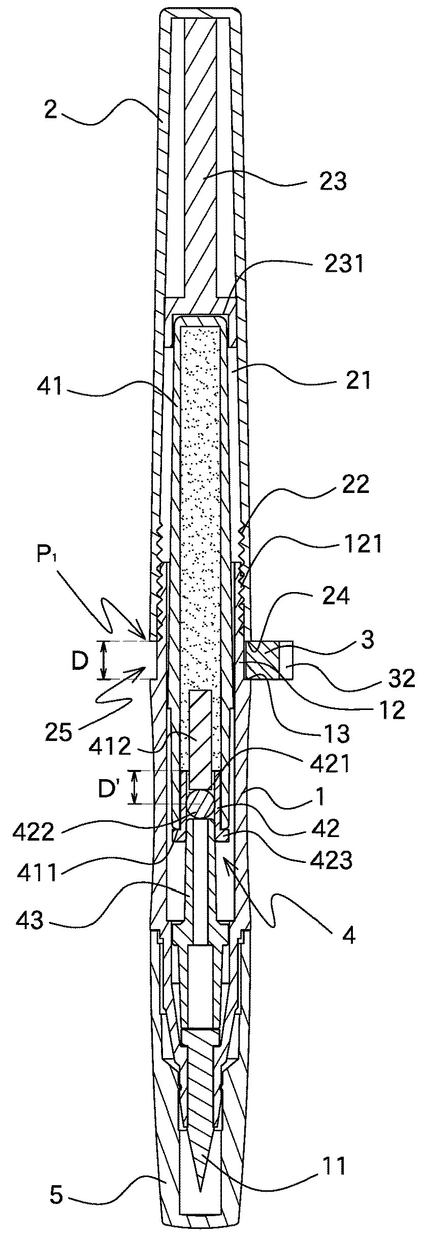
[0027]Referring to FIGS. 1 to 3, the cosmetic applicator of the present invention comprises a body 1 having a space defined axially therein. A tip part 11 is connected to the first end of the body 1, and an extension 12 extends from the second end of the body 1 and has a threaded portion 121 formed thereon. The body 1 has a shoulder 13 formed at the conjunction portion between the extension 12 and the body 1. The diameter of the shoulder 13 is larger than that of the threaded portion 121.

[0028]A case 2 is connected to the body 1 and has a room 21 which communicates with the space of the body 1. A rotary member 22 is threadedly connected to the threaded portion 121 of the body 1. A contact member 23 is received in the room 21 of the case 2. In this embodiment, the contact member 23 is a T-shaped member. The case 2 has a contact portion 24 which is located corresponding to the shoulder 13 of the body 1. In a preferable embodiment, the contact member 23 and the case 2 are a one-piece p...


PUM


Abstract

A cosmetic applicator includes a body which includes a tip part and an extension which has a threaded portion. A case has a rotary member threadedly connected to the threaded portion. A contact member is received in the case which has a contact portion located corresponding to the shoulder of the body. A liquid supply unit is axially received in the body and the case, and has a liquid tube, a duct and a guide tube. The liquid tube contacts the contact member. The duct is inserted in the liquid tube and has a passage. A sealing member is removably located at the duct to seal or open the passage. A clip is connected to a groove between the case and the body before first use. The clip is removed and the case is rotated to move the sealing member to allow cosmetic liquid to reach the tip part.

Description

BACKGROUND OF THE INVENTION1. Fields of the Invention[0001]The present invention relates to a cosmetic applicator with a rotary cartridge, and more particularly, to a cosmetic applicator wherein the liquid received therein evenly reaches the applicator by wat of rotation and shaking when the applicator is first used.2. Descriptions of Related Art[0002]Generally speaking, makeup application is a common courtesy for people to maintain basic mannerism, as well as appealing appearances. Among different types of cosmetic applicators, a cosmetic applicator with a space for receiving cosmetic liquid is needed.[0003]The conventional cosmetic applicator known to applicant is a push-type applicator and generally comprises a body and a cap, wherein cosmetic material such as cosmetic liquid is received in a cartridge in the body. A button is connected to the rear end of the body and a tip part is connected to the front end of the body. A resilient member is located between the cartridge and the...

Claims


Application Information

Patent Timeline
Patent Type & Authority Applications(United States)
IPC IPC(8): A45D34/04B43K8/04
CPCB43K8/04A45D34/04A45D2034/005A45D2040/208B43K5/1827B43K5/1863B43K7/10B43K8/12
Inventor LU, HSIU-OU
Owner MEI SHUAL COSMETICS
Why Eureka
Try Eureka