Vehicle front structure
a front structure and vehicle technology, applied in the field of vehicle front structure, can solve problems such as inefficient distribution of load, and achieve the effect of relieving stress concentration
- Summary
- Abstract
- Description
- Claims
- Application Information
AI Technical Summary
Benefits of technology
Problems solved by technology
Method used
Image

Examples
first embodiment
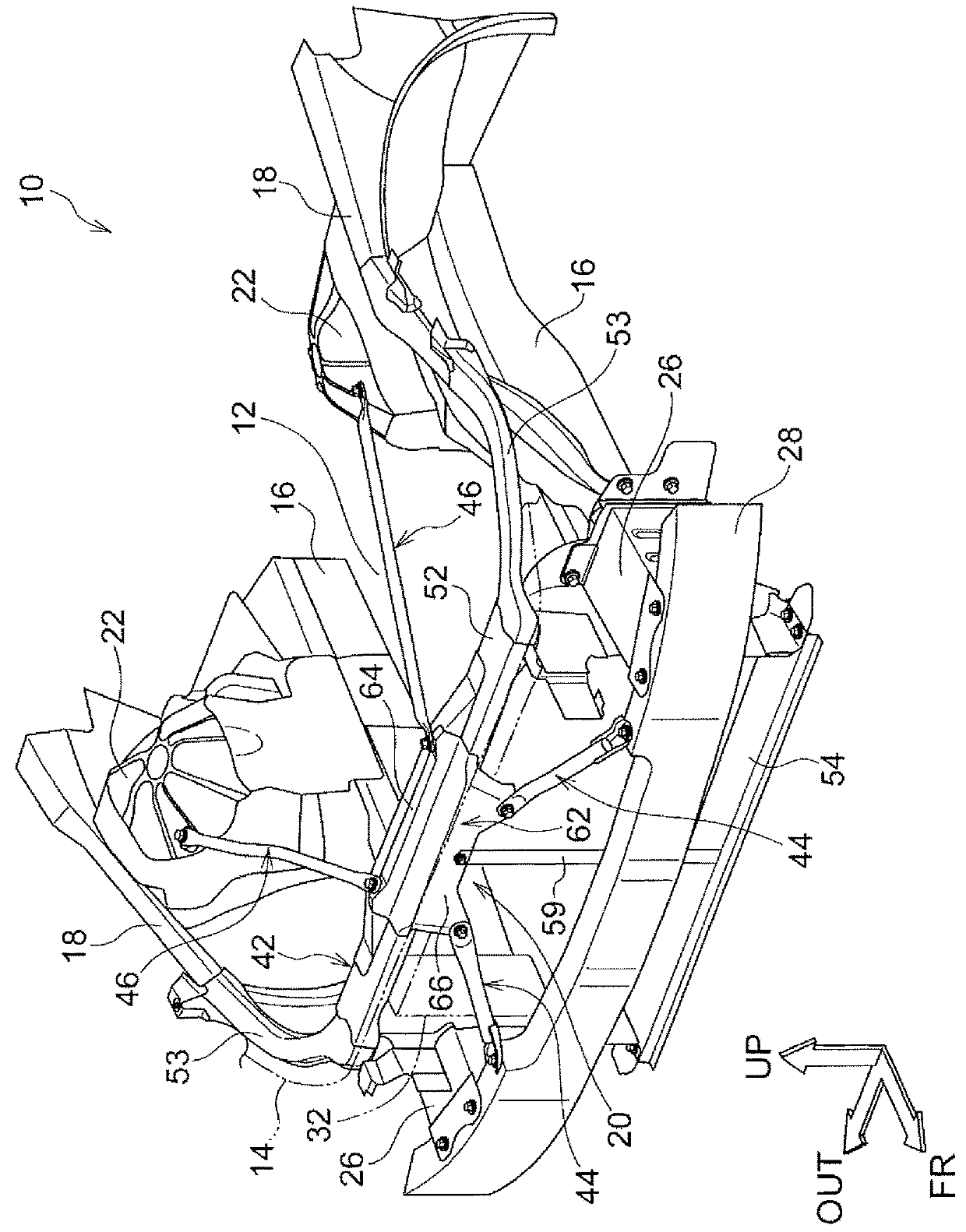
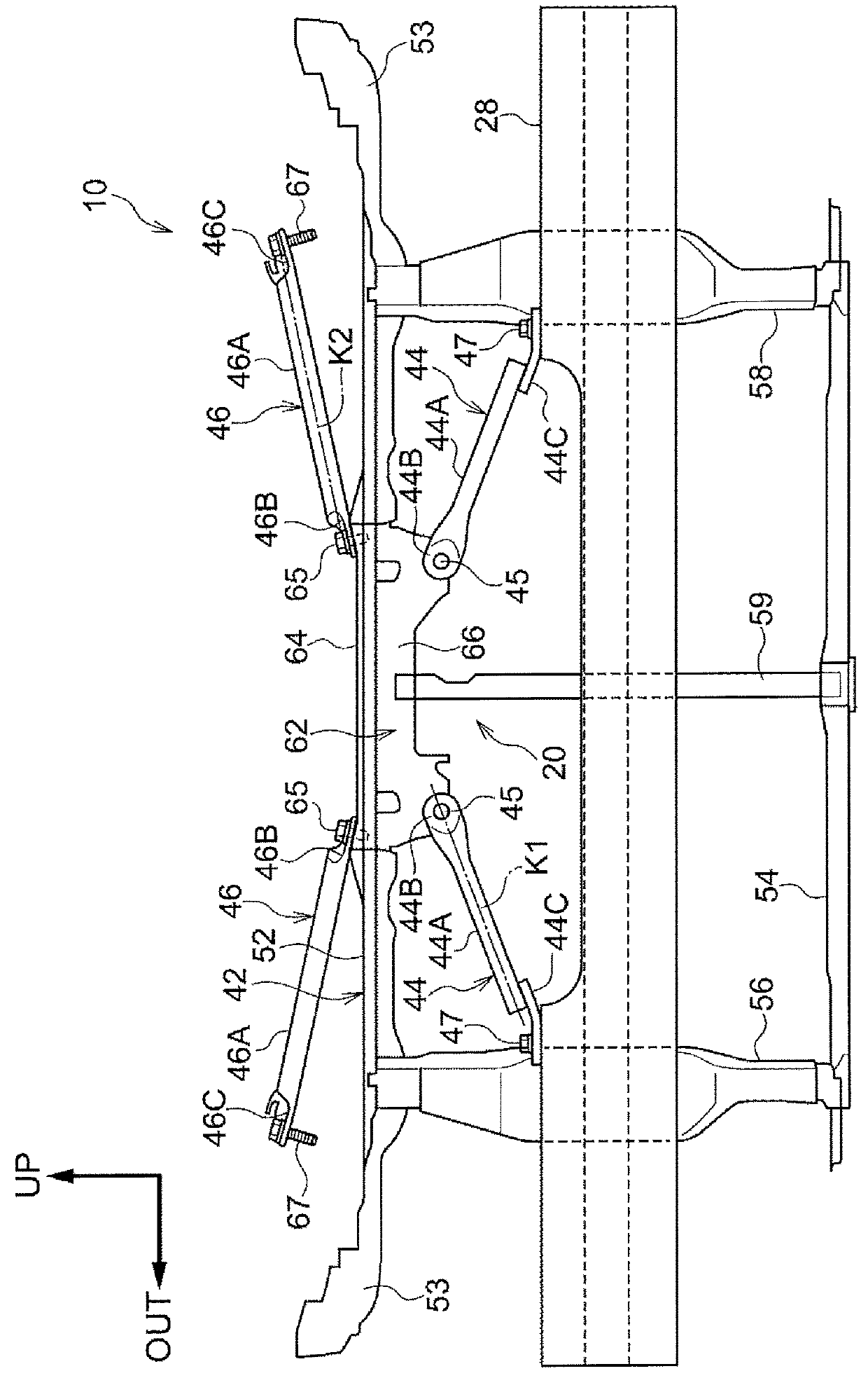
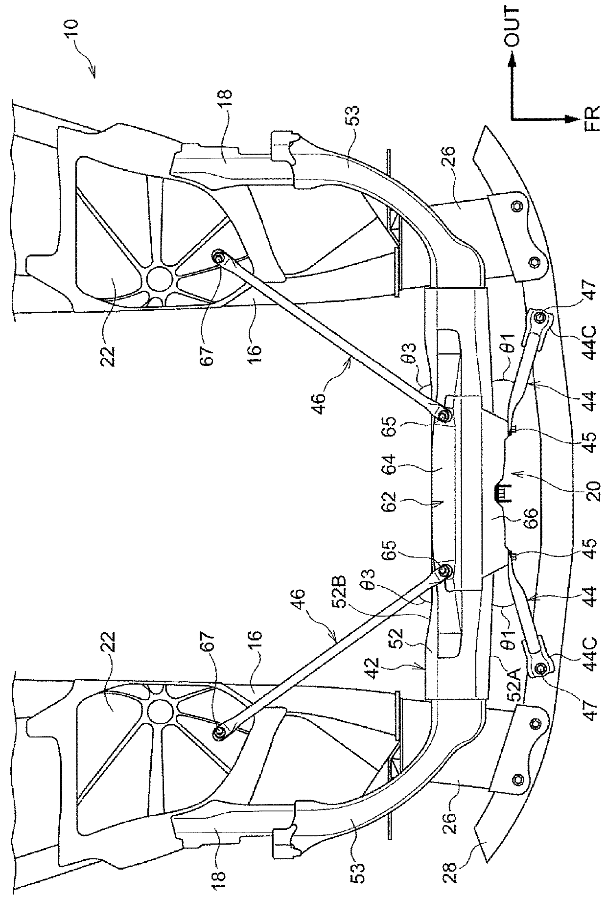
[0030]Hereinafter, a vehicle 10 and a vehicle front structure 20 according to a first embodiment will be described with reference to FIG. 1 to FIG. 5A. In each drawing, the arrow FR indicates a vehicle front side, the arrow OUT indicates an outer side in a vehicle width direction, and the arrow UP indicates a vehicle upper side. Hereinafter, when an upper side and a lower side are simply described, the upper side and the lower side respectively indicate an upper side and a lower side in a vehicle vertical direction. When a right side and a left side are simply described, the right side and the left side respectively indicate a right side and a left side in the vehicle width direction in a situation in which the vehicle 10 is viewed from the front. A vehicle longitudinal direction, the vehicle width direction and the vehicle vertical direction are orthogonal to one another.
[0031]As shown in FIG. 1, the vehicle 10 includes the vehicle front structure 20 according to the first embodime...
second embodiment
[0067]Next, a vehicle front structure 70 according to a second embodiment will be described.
[0068]FIG. 6 schematically shows the vehicle front structure 70. The vehicle front structure 70 is provided in the vehicle 10 (see FIG. 1) according to the first embodiment instead of the vehicle front structure 20 (see FIG. 1). Like reference numerals denote members and portions in the vehicle front structure 70, basically the same as the members and portions of the above-described first embodiment, and the description thereof is omitted.
[0069]The vehicle front structure 70 includes the radiator support upper 52, the two first braces 44, the two second braces 46, the center brace 59 and the center bracket 62. The vehicle front structure 70 differs from the vehicle front structure 20 only in the radiator support upper 52-side connected position of each second brace 46. In the vehicle front structure 70, the first brace 44 are respectively provided on both sides in the vehicle width direction,...
third embodiment
[0076]Next, a vehicle front structure 90 according to a third embodiment will be described.
[0077]FIG. 7 shows the vehicle front structure 90 provided in a vehicle 80 according to the third embodiment. The vehicle 80 includes a pair of right and left front side members 82 as an example of side members. Each front side member 82 extends in the vehicle longitudinal direction, and is coupled to a bumper reinforcement (not shown). The side member in the present embodiment includes not only a side member alone but also a side member including a crash box. The vehicle front structure 90 includes a radiator support upper 102, two first braces 94 and two second braces 96. The radiator support upper 102 constitutes part of a radiator support 92. Each first brace 94 serves as an example of a first connection member. Each second brace 96 serves as an example of a second connection member.
[0078]The radiator support 92 includes the radiator support upper 102, a radiator support lower 104, and rad...
PUM
 Abstract
Description
Claims
Application Information
 - R&D
- Intellectual Property
- Life Sciences
- Materials
- Tech Scout
- Unparalleled Data Quality
- Higher Quality Content
- 60% Fewer Hallucinations
Browse by: Latest US Patents, China's latest patents, Technical Efficacy Thesaurus, Application Domain, Technology Topic, Popular Technical Reports.
© 2025 PatSnap. All rights reserved.Legal|Privacy policy|Modern Slavery Act Transparency Statement|Sitemap|About US| Contact US: help@patsnap.com