Supercharge Your Innovation With Domain-Expert AI Agents!

Exhaust gas purification apparatus for an internal combustion engine

Active Publication Date: 2018-06-28
TOYOTA JIDOSHA KK
View PDF5 Cites 2 Cited by
  • Summary
  • Abstract
  • Description
  • Claims
  • Application Information

AI Technical Summary

Benefits of technology

This patent presents a method to give a reducing agent to an NOx catalyst without creating more NOx through oxidation of ammonia.

Problems solved by technology

When ammonia decreases due to the oxidation of ammonia, ammonia runs short in the NOx catalyst, so it can become difficult to remove or reduce NOx.

Method used


Image

  • Exhaust gas purification apparatus for an internal combustion engine
  • Exhaust gas purification apparatus for an internal combustion engine
  • Exhaust gas purification apparatus for an internal combustion engine

Examples


first embodiment

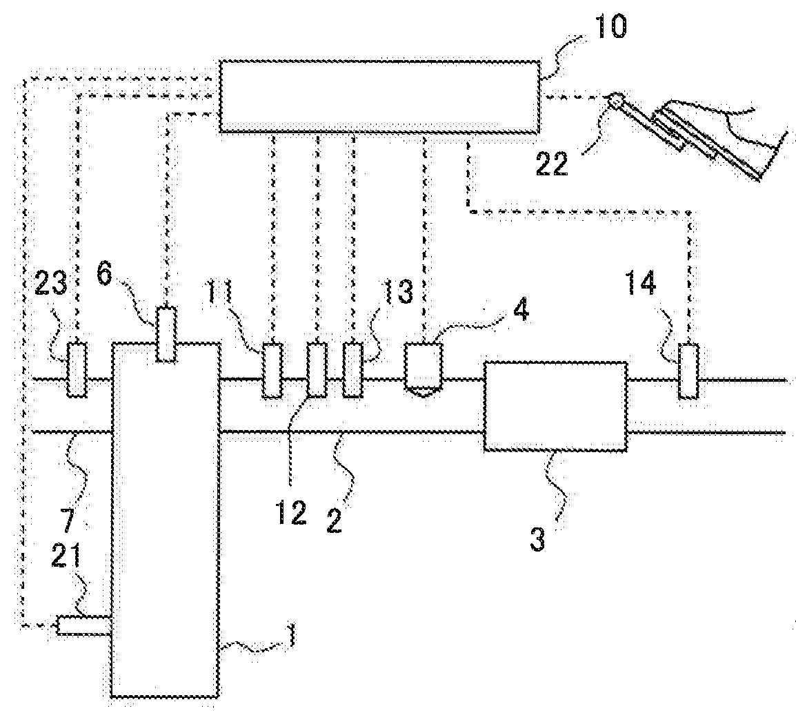
[0042]FIG. 1 is a view showing the schematic construction of an internal combustion engine and its exhaust system according to a first embodiment of the present disclosure. The internal combustion engine 1 is a diesel engine for driving a vehicle. However, the internal combustion engine1 may be a gasoline engine. An exhaust passage 2 is connected to the internal combustion engine 1. In the exhaust passage 2, there is arranged an NOx selective catalytic reduction catalyst 3 (hereinafter, referred to as an “NOx catalyst 3”) which serves to selectively reduce NOx in an exhaust gas with the use of ammonia as a reducing agent.

[0043]In the exhaust passage 2 at the upstream side of the NOx catalyst 3, there is arranged an addition valve 4 which serves to add urea water as a precursor of ammonia into an exhaust gas. The urea water added from the addition valve 4 is hydrolyzed into ammonia in the NOx catalyst 3, and the ammonia thus generated is adsorbed to the NOx catalyst 3. This ammonia i...

second embodiment

[0067]In the above-mentioned first embodiment, the air fuel ratio of the exhaust gas becomes equal to or less than the predetermined air fuel ratio, only at the time of high load operation such as acceleration, etc. For that reason, when light load operation continues, the equivalent ratio can not be made large, so the NOx reduction rate may drop. Accordingly, in a second embodiment of the present disclosure, in cases where the amount of adsorption of ammonia in an NOx catalyst 3 is smaller than a predetermined amount of adsorption, the air fuel ratio of the exhaust gas flowing into the NOx catalyst 3 is actively made smaller than the predetermined air fuel ratio. The predetermined amount of adsorption is an amount of adsorption of ammonia in the NOx catalyst 3 in which the NOx reduction rate falls within an allowable range. The predetermined amount of adsorption has been obtained in advance through experiments, simulations or the like. In this manner, by actively making the air fue...

third embodiment

[0080]FIG. 9 is a view showing the schematic construction of an internal combustion engine and its exhaust system according to a third embodiment of the present disclosure. In the following, a construction different from that shown in FIG. 1 will mainly be explained. An internal combustion engine 1 according to this third embodiment is mounted on a hybrid vehicle 10. In addition, a generator 101 is mounted on the hybrid vehicle 100. With the hybrid vehicle 100, electricity or electric power can be generated by means of the generator 101 using the internal combustion engine 1 as a power source. A battery 102 is connected to the generator 101 through electrical wiring. Also, an ECU is connected to the generator 101 through electrical wiring, so that the generator 101 is controlled by means of the ECU 10.

[0081]In this third embodiment, as a technique to increase the air fuel ratio of exhaust gas, there is adopted a technique to increase the torque produced by the internal combustion en...


PUM


Abstract

A reducing agent is supplied to an NOx selective catalytic reduction catalyst in a suitable manner, while suppressing NOx from being produced by oxidation of ammonia in the NOx catalyst. In cases where the temperature of the NOx catalyst is equal to or higher than a predetermined temperature at which ammonia is oxidized, an amount of the reducing agent to be supplied to the NOx catalyst is made larger, when an air fuel ratio of exhaust gas flowing into the NOx catalyst is small, than it is large.

Description

CROSS REFERENCE TO RELATED APPLICATIONS[0001]This application claims priority to Japanese Patent Application No. 2016-252592 filed on Dec. 27, 2016 the entire contents of which are incorporated by reference herein.TECHNICAL FIELD[0002]The present disclosure relates to an exhaust gas purification apparatus for an internal combustion engine.DESCRIPTION OF THE RELATED ART[0003]There has been known an NOx selective catalytic reduction catalyst (hereinafter, also referred to simply as an “NOx catalyst”) which purifies (removes or reduces) NOx contained in an exhaust gas from an internal combustion engine by using ammonia as a reducing agent. At the upstream side of this NOx catalyst, there is arranged an addition valve or the like which serves to add ammonia or a precursor of ammonia (hereinafter, ammonia or a precursor thereof being also referred to as an “additive agent”) into the exhaust gas. As the precursor of ammonia, there can be mentioned urea, for example.[0004]Here, in cases wh...

Claims


Application Information

Patent Timeline
IPC IPC(8): F01N3/20F01N11/00F02B63/04H02K7/18B01D53/94
CPCF01N3/208F01N11/002F01N11/007F02B63/04H02K7/1815B01D53/9418B01D53/9495F01N2610/02F01N2560/06F01N2560/025F01N3/2066F01N2550/02F01N2900/1402F01N2900/1404F01N2900/1602Y02T10/12Y02T10/40
Inventor MATSUMOTO, ARIFUMI
Owner TOYOTA JIDOSHA KK
Features
  • R&D
  • Intellectual Property
  • Life Sciences
  • Materials
  • Tech Scout
  • Unparalleled Data Quality
  • Higher Quality Content
  • 60% Fewer Hallucinations
Learn More