

Control Device for Vehicle Drive System
- Summary
- Abstract
- Description
- Claims
- Application Information
AI Technical Summary
Benefits of technology
Problems solved by technology
Method used
Image

Examples
first embodiment
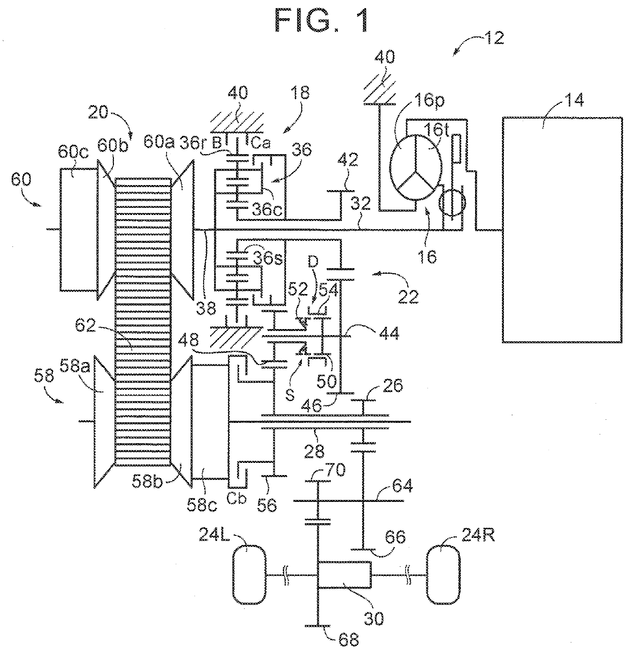
[0030]FIG. 1 is a skeletal diagram for describing a schematic configuration of a vehicle drive system 12 (hereinafter, referred to as the drive system 12) that is a first embodiment as one example of the present disclosure. The drive system 12 includes, for example, an engine (drive power source) 14 used as a drive power source for traveling, a torque converter 16 as a hydraulic power transmission device, a forward and reverse traveling switching device 18, a belt continuously variable transmission mechanism 20, a gear power transmission mechanism 22, an output shaft 28 integrated with an output gear 26 connected to drive wheels 24L, 24R in a manner capable of transmitting power to the drive wheels 24L, 24R, and a differential gear 30. The output shaft 28 is connected to the drive wheels 24L, 24R in a manner capable of transmitting (outputting) torque transmitted to the output shaft 28 as power to the drive wheels 24L, 24R. The drive system 12 includes the continuously variable tran...
second embodiment
[0089]FIG. 7 is a flowchart describing one example of a control operation in the electronic control unit of the second embodiment when the accelerator pedal is stepped on during traveling in, for example, the belt traveling mode.
[0090]In the flowchart in FIG. 7, in S20 that corresponds to the function of the clutch switching controller 96, a determination is performed as to whether or not the power ON traveling in which the accelerator pedal is stepped on to increase the base target turbine rotational speed ntb* (rpm) above the upper limit guard value Gmax (rpm) is performed. When a positive determination is made in S20, a determination as to whether or not the downshift target turbine rotational speed nt*dw (rpm) is less than the downshift turbine rotational speed ntdw (rpm) (nt*dw21 that corresponds to the function of the clutch switching controller 96. When a positive determination is made in S21, execution of a clutch-to-clutch shift that engages the forward traveling clutch Ca ...
PUM
 Abstract
Description
Claims
Application Information