Water Injection Device

Active Publication Date: 2018-06-28
HITACHI-GE NUCLEAR ENERGY LTD +1
View PDF0 Cites 0 Cited by
  • Summary
  • Abstract
  • Description
  • Claims
  • Application Information

AI Technical Summary

Benefits of technology

[0012]According to the present invention, a high reliable water injection device which injects water into a reactor containment vessel and can reliably shut off cooling water at normal times and quickly and reliably inject water into the reac

Problems solved by technology

In water-cooled reactors, if cooling water is lost due to stoppage of feed water into a reactor pressure vessel or breakage of a pipe connected to the reactor pressure vessel, the reactor water level drops, a core is exposed, and thus there is a possibility that cooling becomes insufficient.
However, although it is extremely low probability, it can be also assumed that the emergency core cooling device is not operated and other water injection devices to core cannot be used.
In such a case, it is considered that the

Method used


Image

  • Water Injection Device
  • Water Injection Device
  • Water Injection Device

Examples


example 1

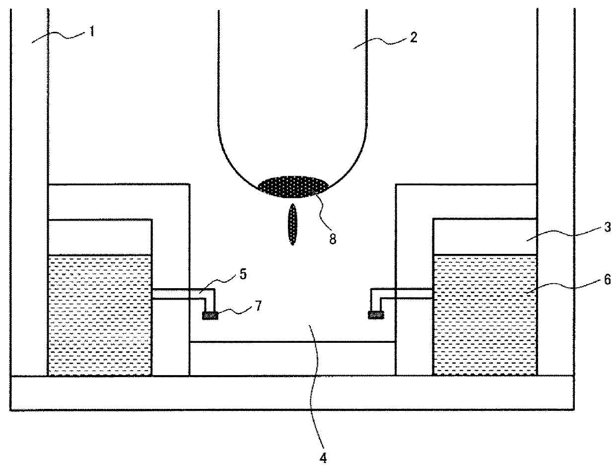
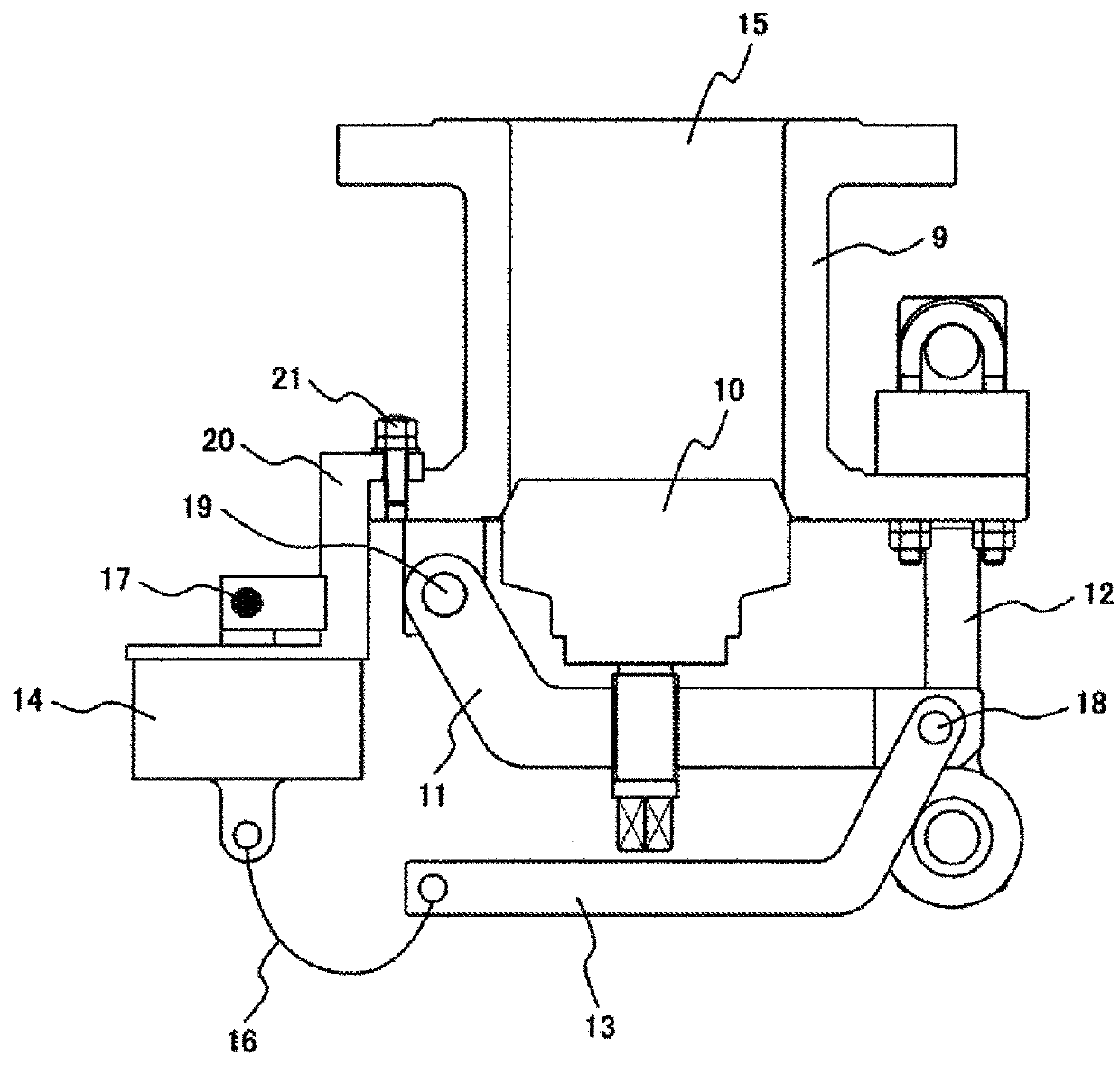
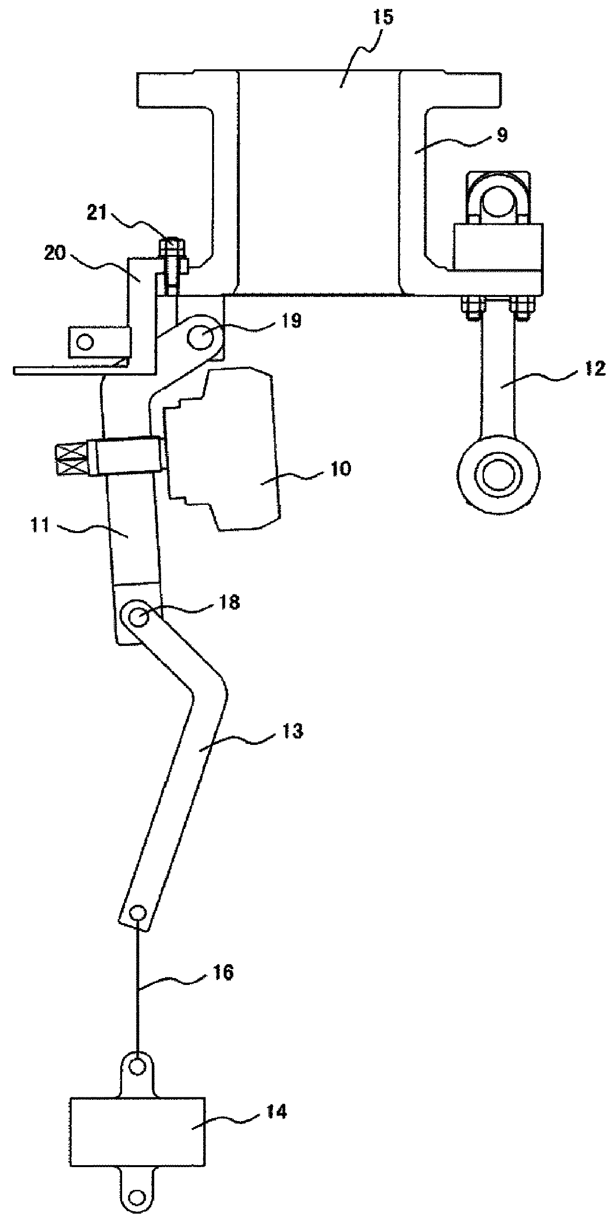
[0019]Hereinafter, one example of the present invention will be described with reference to FIG. 1 to FIG. 3. FIG. 1 is a schematic diagram of a nuclear power plant (reactor containment vessel) including a water injection device in this example. FIG. 2 and FIG. 3 are cross-sectional views illustrating the water injection device of this example, FIG. 2 illustrates a state before the water injection device opens a flow path and FIG. 3 illustrates a state where the water injection device opens the flow path.

[0020]As illustrated in FIG. 1, the nuclear power plant includes a reactor pressure vessel 2 which is installed in a reactor containment vessel 1, a suppression pool (pressure suppression pool) 3, a lower dry well 4, and a pipe 5 which connects the suppression pool 3 and the lower dry well 4 to each other. The cooling water 6 in the suppression pool 3 flows into the lower dry well 4 via the pipe 5.

[0021]At an end portion of the pipe 5 on the lower dry well 4 side, a water injection ...

example 2

[0035]With reference to FIG. 4, a water injection device of Example 2 will be described. FIG. 4 illustrates a modification example of the water injection device illustrated in FIG. 2 and is an example in which a seal weld 22 is formed by welding with a low melting point alloy at the close contact portion between the body 9 and the disk 10 and the sealing performance (closing performance) of the flow path 15 by the disk 10 is improved.

[0036]When the flow path 15 is closed using the disk 10, the disk 10 is constantly receiving the water pressure from the cooling water in the flow path 15, and due to aged deterioration, there is a concern about leakage of the cooling water from the close contact portion (joint portion) between the body 9 and the disk 10 or the like. In addition, it is also assumed that an unfamiliar operator mistakenly pulls out the pin 17 and unnecessary water injection may be performed.

[0037]Therefore, in addition to supporting the swing arm 11 and the disk 10 by the...


PUM


Abstract

A high reliable water injection device is provided that injects water into a reactor containment vessel and can reliably shut off cooling water at normal times and quickly and reliably inject water into the reactor containment vessel without the need for external power, in a case of emergency. The water injection device injects water into a reactor containment vessel includes a flow path through which cooling water is supplied; a disk that closes the flow path; a swing arm that is connected to the disk and performs closing and opening of the flow path by the disk; and a weight that is connected to the swing arm via a swing lever, in which the weight is supported by a support member made of a low melting point alloy.

Description

CLAIM OF PRIORITY[0001]The present application claims priority from Japanese Patent application serial no. 2016-250974, filed on Dec. 26, 2016, the content of which is hereby incorporated by reference into this application.TECHNICAL FIELD[0002]The present invention relates to a structure of a reactor containment vessel, and in particular, to an effective technique that is applied to a water injection device which injects water into a reactor containment vessel in an emergency.BACKGROUND ART[0003]In water-cooled reactors, if cooling water is lost due to stoppage of feed water into a reactor pressure vessel or breakage of a pipe connected to the reactor pressure vessel, the reactor water level drops, a core is exposed, and thus there is a possibility that cooling becomes insufficient. Assuming such a case, an emergency stop of the reactor is automatically performed by the signal of the water level drop, the core is flooded and cooled by injection of cooling water by an emergency core ...

Claims


Application Information

Patent Timeline
IPC IPC(8): G21C15/18G21C15/243
CPCG21C15/18G21C15/243G21Y2002/207G21Y2004/30G21C9/016G21C15/185Y02E30/30F16K17/383F16K17/386G21C9/00G21C13/10
Inventor HIRASAWA, DAISUKEKIYOTOKI, YOSHIHISASATOU, HISASHISAKEMURA, KEISUKESASAKI, KEIJIFUKUDA, YUTA
Owner HITACHI-GE NUCLEAR ENERGY LTD
Why Eureka
Try Eureka