Load drive device

a technology of a drive device and a load, which is applied in the direction of electrical equipment, ac motor control, control systems, etc., can solve the problems of sudden and excessive load of motors, drive circuits that may break down thermally or electrically, etc., and achieve the effect of reducing the cost of the ecu circuit and the heat dissipation devi

Inactive Publication Date: 2018-06-28
HITACHI ASTEMO LTD
View PDF0 Cites 2 Cited by
  • Summary
  • Abstract
  • Description
  • Claims
  • Application Information

AI Technical Summary

Benefits of technology

[0036]According to the present invention, for example, the value in voltage rise and the value in temperature rise between the elements of each of the switching elements included in the H-bridge circuit, both can be reduced. Therefore, for example, the product specifications required by customers, can be satisfied. For example, in a case where the capacitor is required to switch from a conventional field capacitor to a ceramic capacitor smaller than the field capacitor in capacitance, in order to satisfy the requirements of miniaturization and cost reduction of the devices of the customers, it is difficult to inhibit the circuit elements from electrically or thermally destroying only with simple capacitor replacement. It is also difficult to inhibit the ceramic capacitor having the small capacitance from electrically breaking down or destroying. However, according to the present invention, therefore, the capacitor 17 as a circuit element can switch from the electrolytic capacitor to the ceramic capacitor and additionally reduction of the heat dissipation device for the H-bridge circuit can be made with the devising of the control method and the load drive method described above. With this arrangement, the H-bridge drive circuit can be miniaturized and cost reduction of the ECU circuit can be achieved.

Problems solved by technology

For example, it is assumed that a motor is suddenly and excessively loaded.
When the motor being loaded is left, the drive circuit thereof may break down thermally or electrically.

Method used


Image

  • Load drive device
  • Load drive device
  • Load drive device

Examples


first embodiment

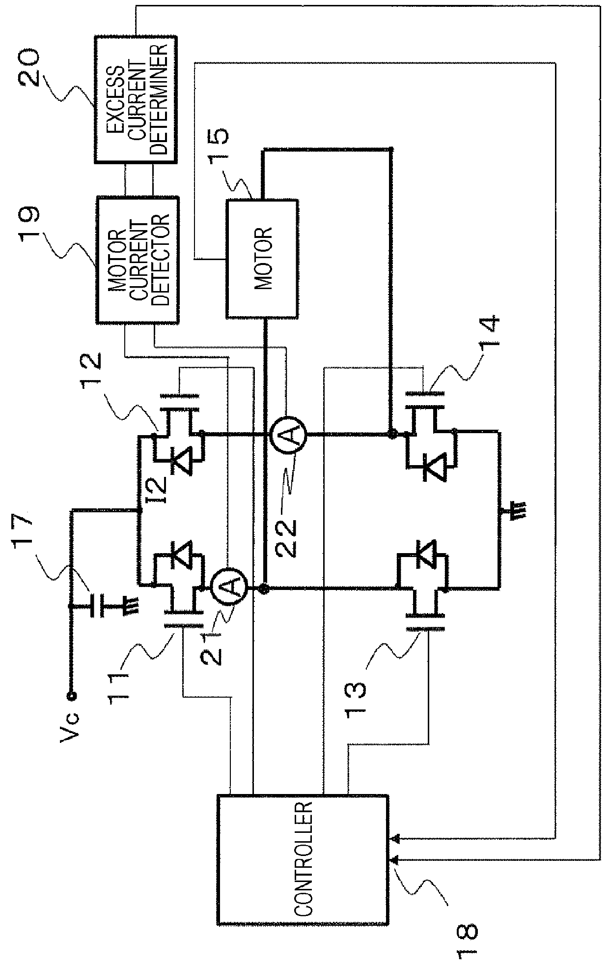
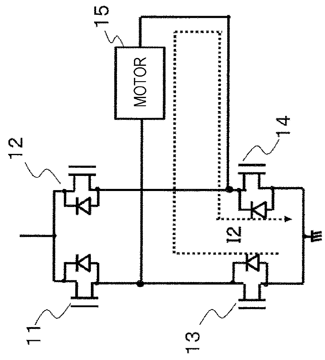
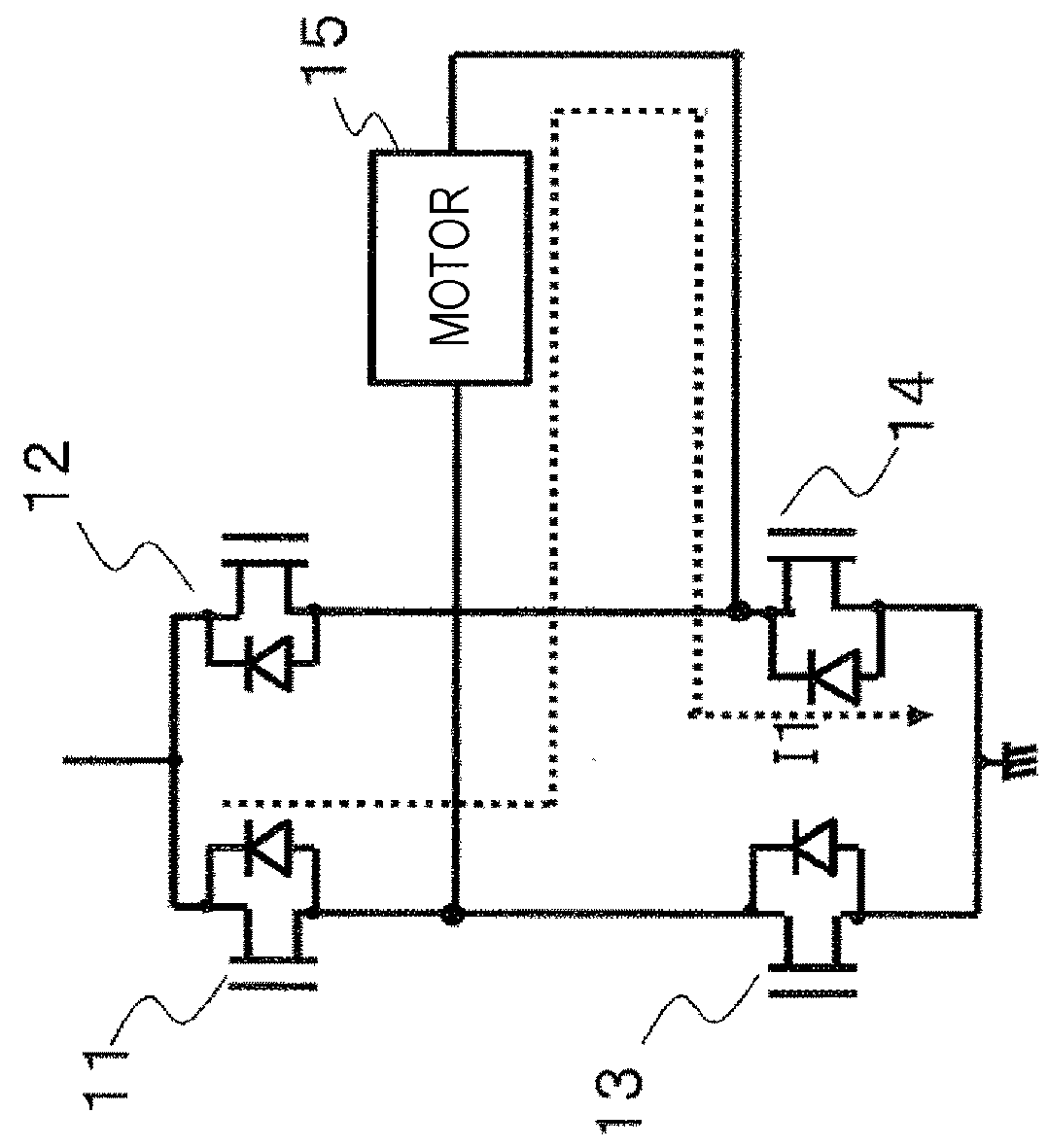
[0064]FIG. 5 illustrates a circuit configuration of a motor-drive H-bridge drive circuit according to a first embodiment.

[0065]The motor-drive H-bridge drive circuit according to the first embodiment, includes a controller 29, switching elements 11, 12, 13, and 14 each having a body diode, a motor mechanism 15, a capacitor 23, a motor current detector 19, a determiner 35, a positive-rotation motor current sensing unit 21, and a negative-rotation motor current sensing unit 22. Note that the body diodes are preferably connected to the switching elements 11 to 14 so as to have a direction illustrated in FIG. 5. The body diodes are connected in parallel to the switching elements as illustrated so that the body diodes each allow a current to flow through the illustrated portion in an upper direction even in a case where the switching elements are turned OFF.

[0066]The capacitor 23 and the switching elements 11, 12, 13, and 14 each having the body diode, the positive-rotation motor current...

second embodiment

[0111]For the first embodiment, a circuit that measures the voltage across the capacitor 23 is required to be added. With this arrangement, the area of the H-bridge drive circuit device (e.g., the area of a circuit board) may increase. According to the present embodiment, a current flowing through a motor 15 is measured without a voltage measurement circuit of a capacitor 23 so that mode switching is achieved.

[0112]FIG. 10 is a diagram of a configuration according to a second embodiment. The same constituent elements in FIGS. 10, 5, and 1 are denoted with the same reference signs.

[0113]FIG. 10 illustrates a circuit configuration of a motor-drive H-bridge drive circuit according to the second embodiment.

[0114]The motor-drive H-bridge drive circuit according to the second embodiment, includes a controller 29, switching elements 11, 12, 13, and 14 each having a body diode, a motor mechanism 15, the capacitor 23, a motor current detector 25, a determiner 26, and a motor current sensing ...

third embodiment

[0140]For the second embodiment, the motor current is required to be measured and the motor current sensing unit 24 is required to be provided for the measurement. Typically, the resistor is used to form the motor current sensing unit 24. However, with this arrangement, the loss of the electrical energy of the H-bridge drive circuit increases. The present embodiment is to improve the problem.

[0141]FIG. 15 is a diagram of a configuration according to a third embodiment. The same constituent elements in FIGS. 15, 10, 5, and 1 are denoted with the same reference signs.

[0142]FIG. 15 illustrates a circuit configuration of a motor-drive H-bridge drive circuit according to the third embodiment.

[0143]The motor-drive H-bridge drive circuit according to the third embodiment, includes a controller 29, switching elements 11, 12, 13, and 14 each provided with a body diode, a motor mechanism 15, a capacitor 23, a motor current detector 19, a determiner 31, a positive-rotation motor current sensin...


PUM


Abstract

To achieve, in a load drive device including an H-bridge circuit, miniaturization of a capacitor or/and the constituent elements of the H-bridge circuit (e.g., reduction in volume) with circuit elements, for example, switching elements included in the H-bridge circuit, being inhibited from breaking down or destroying even in a case where a load is overloaded. The invention is disclosed in which, as a solution to the achievement, first and second modes are provided as a switching mode for the switching elements 11, 12, 13, and 14 and switching is appropriately performed between the first and second modes.

Description

TECHNICAL FIELD[0001]The present invention relates to a load drive device, and particularly relates to a load drive device that drives a load including a coil (e.g., an electric motor). For example, the present invention relates to a motor drive device applied to an electronic throttle control device in a motor vehicle.BACKGROUND ART[0002]A drive device using an H-bridge drive circuit, has been known as a drive device that drives a motor including a coil. The motor drive device using the H-bridge drive circuit, includes four switching elements diagonally connected to the motor to cross each other, and turns the switching elements ON or OFF in a predetermined duty cycle so that the operation state of the motor (positive rotation, negative rotation, and stop) can be controlled.[0003]In making a switch from the operation state of the positive rotation or the negative rotation to the state of the stop, energy that has been stored and remains in the coil in the motor, is required to be d...

Claims


Application Information

Patent Timeline
Patent Type & Authority Applications(United States)
IPC IPC(8): H02P27/06H02P29/024
CPCH02P27/06H02P29/027H02P3/22
Inventor LIU, MINGYAMAWAKI, TAIZOMAYUZUMI, TAKUYAISHIDA, RYOSUKESUGIYAMA, YASUSHIONO, GOICHI
Owner HITACHI ASTEMO LTD
Why Eureka
Try Eureka