Setting apparatus to set movement path of virtual viewpoint, setting method, and storage medium

a technology of setting apparatus and movement path, which is applied in the direction of image analysis, instruments, computing, etc., can solve problems such as viewer's incongruity feeling

Inactive Publication Date: 2018-06-28
CANON KK
View PDF39 Cites 7 Cited by
  • Summary
  • Abstract
  • Description
  • Claims
  • Application Information

AI Technical Summary

Benefits of technology

[0004]The present invention is a setting apparatus that sets a movement path of a virtual viewpoint, the setting apparatus including: a specification unit configured to specify one or a plurality of virtual viewpoints and an object of interest; and a setting unit configured to set, based on the one or the plurality of virtual viewpoints and the object of interest specified by the specification unit, the movement path of the virtual viewpoint such that a difference of image quality between objects of interest falls within a predetermined range, the object of interest existing in each of a plurality of virtual viewpoint images generated in accordance with the movement path of the virtual viewpoint.

Problems solved by technology

Such a virtual viewpoint video image will give a feeling of incongruity to a viewer, and therefore, undesirable.

Method used


Image

  • Setting apparatus to set movement path of virtual viewpoint, setting method, and storage medium
  • Setting apparatus to set movement path of virtual viewpoint, setting method, and storage medium
  • Setting apparatus to set movement path of virtual viewpoint, setting method, and storage medium

Examples


first embodiment

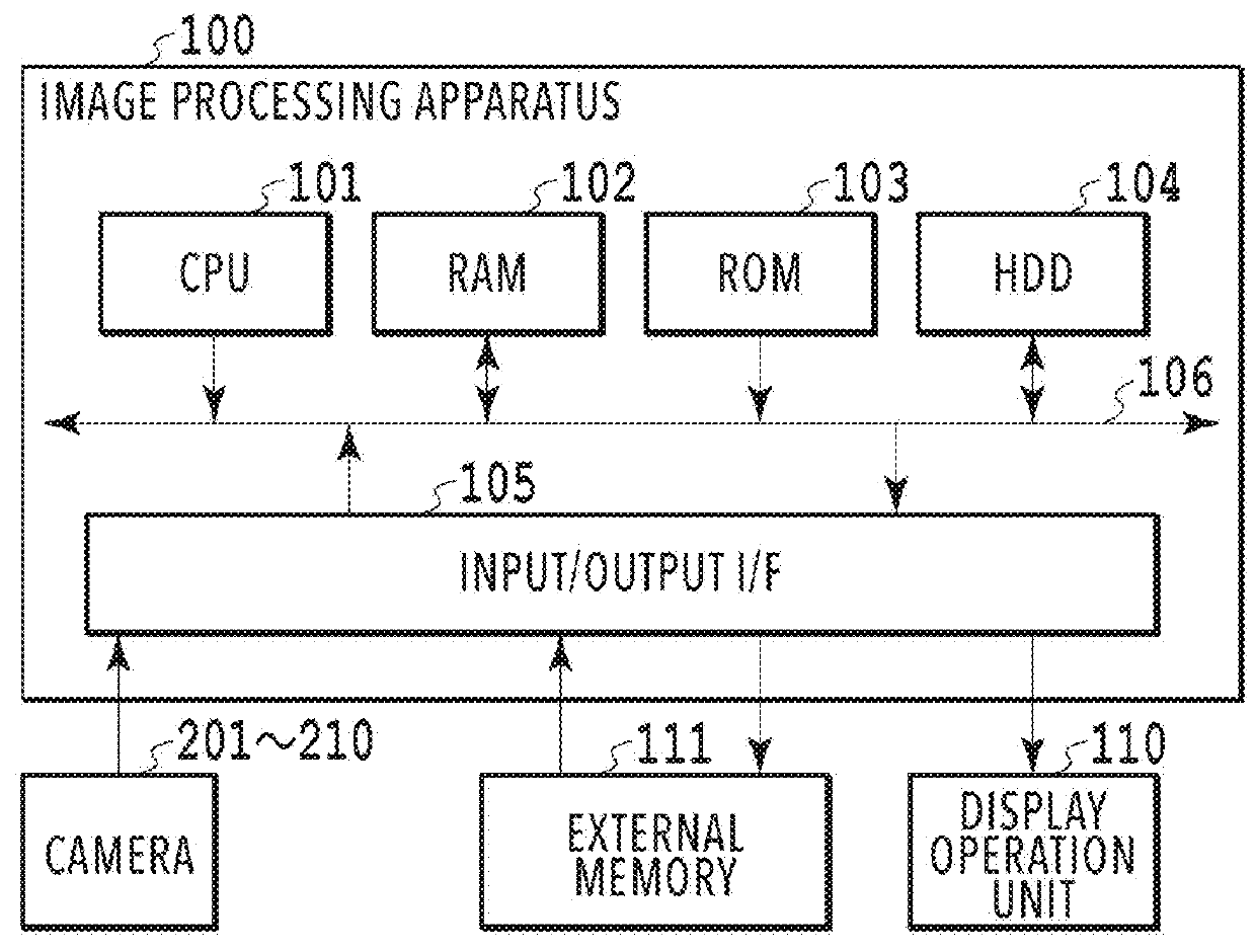
[0021]FIG. 1 is a diagram showing an example of a hardware configuration of an image processing apparatus 100. The image processing apparatus 100 of the present embodiment has a function as a setting apparatus that sets a movement path of a virtual viewpoint. The image processing apparatus 100 includes a CPU 101, a RAM 102, a ROM 103, an HDD 104, and an input / output I / F 105. Then, each unit making up the image processing apparatus 100 is connected to one another by a system bus 106. The image processing apparatus 100 may have each unit shown in FIG. 1 in plurality. Further, the image processing apparatus 100 is connected to cameras 201 to 210, a display operation unit 110, and an external memory 111 via the input / output I / F 105.

[0022]The CPU 101 executes programs stored in the ROM 103 by using the RAM 102 as a work memory and centralizedly controls each unit of the image processing apparatus 100 via the system bus 106. Due to this, various kinds of processing, to be described later,...

second embodiment

[0068]In the first embodiment, the aspect is explained in which a limit focal length within which the blur amount of a virtual viewpoint image falls within an allowable range is found and a camera work is determined based on the limit focal length. Next, an aspect is explained as a second embodiment in which the focal length of a virtual camera is fixed and a user selects an appropriate camera work by using a GUI (Graphical User Interface).

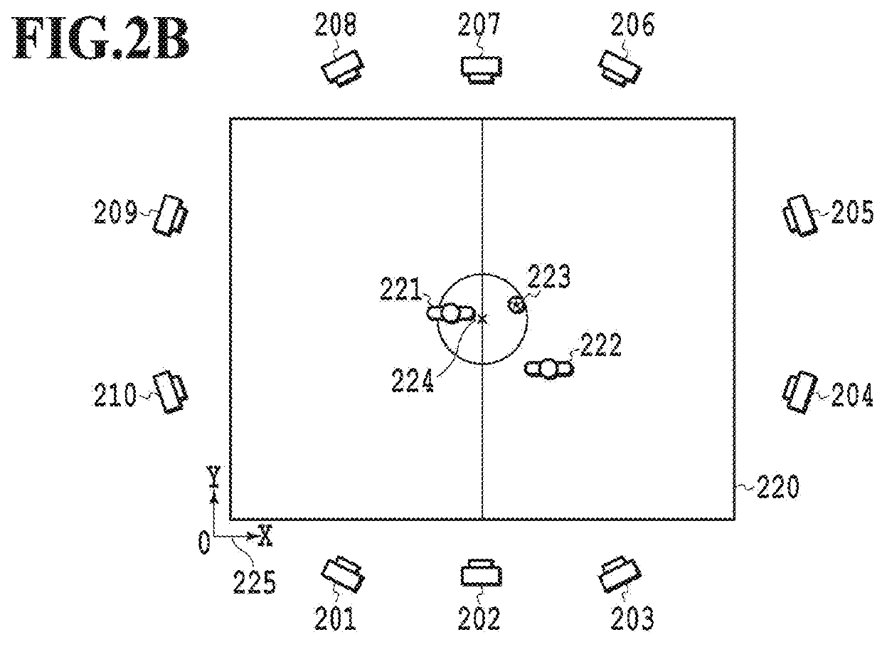
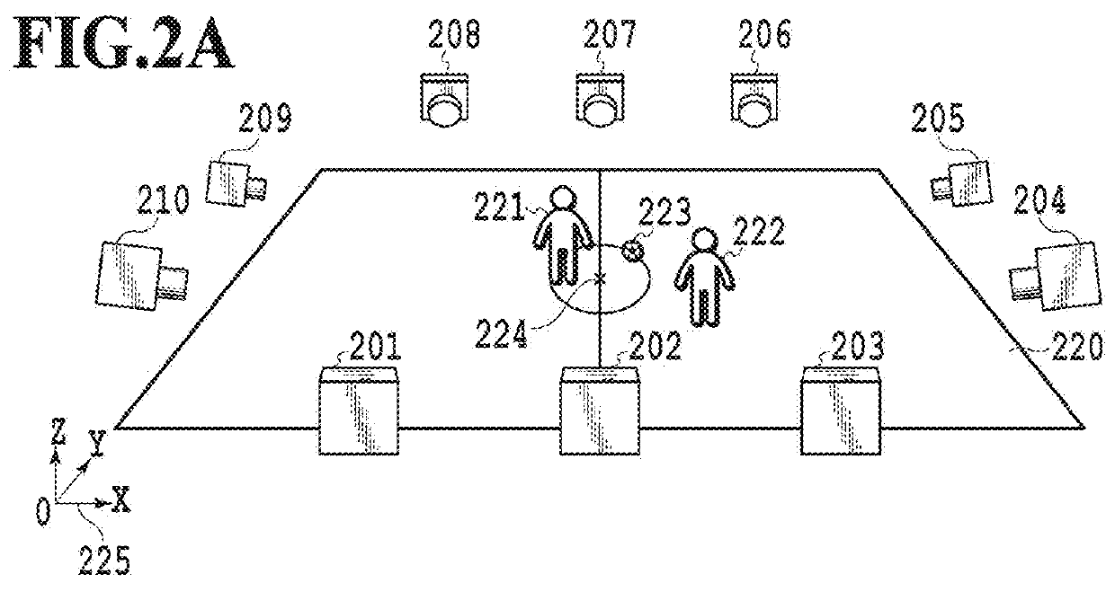
[0069]Explanation of the basic configuration (FIG. 1) of the image processing apparatus and the camera arrangement (FIG. 2A) in common to those of the first embodiment is omitted and in the following, different points are explained mainly.

[0070]FIG. 9 is a function block diagram of an image processing apparatus 100′ according to the present embodiment. The image processing apparatus 100′ further includes a GUT control unit 901, a start point / end point setting unit 902, a limit distance derivation unit 903, and a virtual viewpoint candidate generat...


PUM


Abstract

A setting apparatus that sets a movement path of a virtual viewpoint, the setting apparatus including: a specification unit configured to specify one or a plurality of virtual viewpoints and an object of interest; and a setting unit configured to set, based on the one or the plurality of virtual viewpoints and the object of interest specified by the specification unit, the movement path of the virtual viewpoint such that a difference of image quality between objects of interest falls within a predetermined range, the object of interest existing in each of a plurality of virtual viewpoint images generated in accordance with the movement path of the virtual viewpoint.

Description

BACKGROUND OF THE INVENTIONField of the Invention[0001]The present invention relates to a setting method of a movement path of a virtual viewpoint relating to a virtual viewpoint video image.Description of the Related Art[0002]As a technique to reproduce a video image from a camera (virtual camera) that does not actually exist, which is arranged virtually in a three-dimensional space, by using a multi-viewpoint video image captured by a plurality of real cameras, there is a virtual viewpoint video image technique. As one of generation methods of a virtual viewpoint video image, there is a method of obtaining a virtual viewpoint video image by estimating a three-dimensional shape of an object from a multi-viewpoint video image obtained by capturing images of the object from the positions that surround the object and by performing texture mapping of the captured images onto the surface the three-dimensional shape that is found. At this time, which viewpoint is used for a captured imag...

Claims


Application Information

Patent Timeline
Patent Type & Authority Applications(United States)
IPC IPC(8): G06T7/246G06T7/292G06T7/73G06T15/04
CPCH04N13/282G06T7/248G06T7/292G06T7/73G06T15/04G06T15/205G06T19/003
Inventor YOSHIMURA, KAZUHIROIMAI, AYATO
Owner CANON KK
Why Eureka
Try Eureka