
Method and apparatus for an unmanned aerial vehicle with a 360-degree camera system

a camera system and unmanned aerial vehicle technology, applied in the field of unmanned aerial vehicle (“ uav”) technologies, can solve the problems of increasing the total weight of the hardware, affecting the flight performance or operation duration of the device, and complicated image stitching process

Inactive Publication Date: 2018-07-05
AIRMADA TECH INC
View PDF114 Cites 20 Cited by
  • Summary
  • Abstract
  • Description
  • Claims
  • Application Information

AI Technical Summary

Benefits of technology

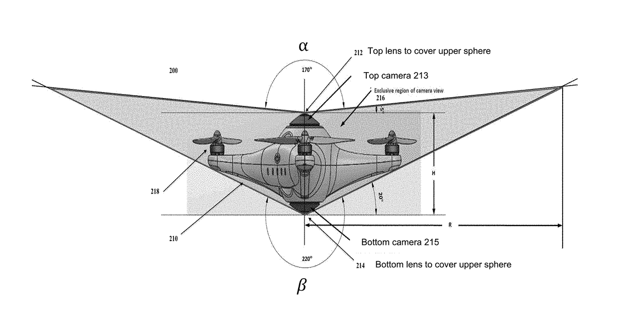
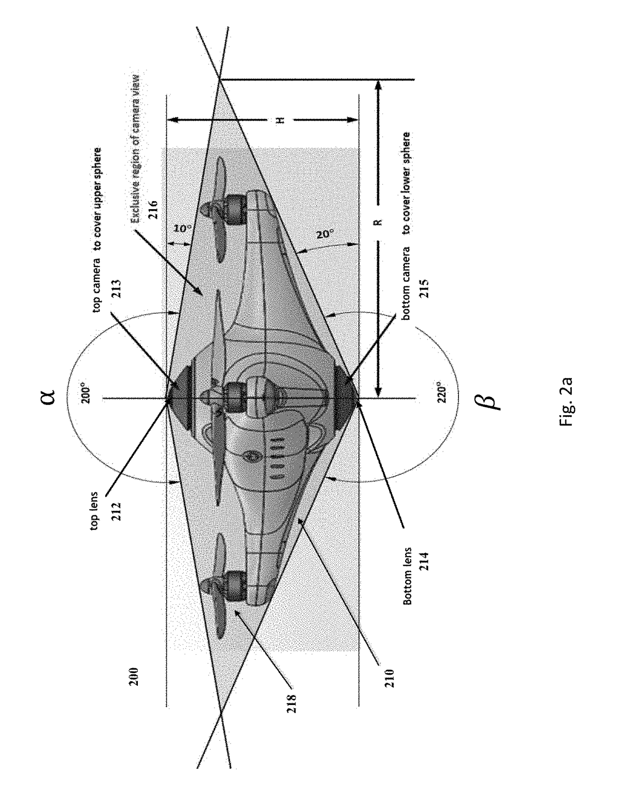
The present invention is about an unmanned aerial vehicle (UAV) that has a 360-degree camera system mounted on it. This system consists of two cameras with different angles of view, which are fixed to the UAV platform. The cameras have extendable lenses that have positions near the corners of the UAV body and are separated by a certain distance. The invention solves the problem of limited visibility in UAVs and provides additional features such as surveillance and mapping. The method for configuring the UAV platform is also provided. The main benefit of the invention is improved visibility and situational awareness for UAVs, which will be useful in various applications like surveillance and mapping.

Problems solved by technology

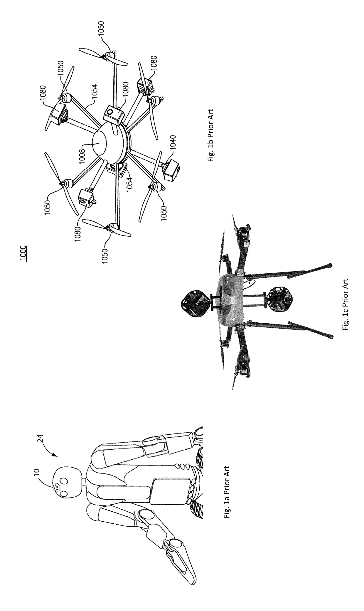
However, such a 360-degree camera usually comprises more than two cameras and lenses, making the image stitching process complicated and the hardware expensive.
Besides the hardware cost, having multiple cameras and lenses also increase the total weight of the hardware, which, in the case of flying devices such as a drone or UAV, would hamper the flight performance or operating duration of these devices.
In addition, as shown in FIG. 1c, many existing UAV devices are installed with landing gears and cameras separate from the body, which makes the devices look cumbersome and unappealing.

Method used


Image

  • Method and apparatus for an unmanned aerial vehicle with a 360-degree camera system
  • Method and apparatus for an unmanned aerial vehicle with a 360-degree camera system
  • Method and apparatus for an unmanned aerial vehicle with a 360-degree camera system

Examples


Embodiment Construction

[0014]The following description is presented to enable a person of ordinary skill in the art to make and use the invention. Descriptions of specific devices, techniques, and applications are provided only as examples. Various modifications to the examples described herein will be readily apparent to those of ordinary skill in the art, and the general principles defined herein may be applied to other examples and applications without departing from the spirit and scope of the invention. Thus, embodiments of the present invention are not intended to be limited to the examples described herein and shown, but is to be accorded the scope consistent with the claims.

[0015]The term “exemplary” is used herein to mean “serving as an example or illustration.” Any aspect or design described herein as “exemplary” is not necessarily to be construed as preferred or advantageous over other aspects or designs.

[0016]Reference will now be made in detail to aspects of the subject technology, examples o...


PUM


Abstract

Described herein is an unmanned aerial vehicle (“UAV”) apparatus comprising a 360-degree camera system mounted onboard a UAV platform. The camera system comprises a pair of cameras with a pair of wide-angle lenses that have a collective angle of view equal to or greater than 360 degrees, and as such, the lenses can capture images of the entire 360-degree spherical space surrounding the apparatus, except for an exclusive region defined by an overlap radius. The overlap radius is calculated using the equation R=H / [tan(α−180 degrees)+tan(β−180 degrees)], wherein α and β are the respective angles of view of the lenses, and H is the vertical distance between the lenses. The UAV platform comprises a body with a symmetric appearance and a retractable landing gear that can retract within the body during flight and extend out at landing.

Description

CROSS-REFERENCE TO RELATED APPLICATIONS[0001]This application claims priority under relevant sections of 35 U.S.C. § 119 to U.S. Provisional Application No. 62 / 440,816, filed on Dec. 30, 2016, which is hereby incorporated by reference in its entirety.FIELD OF THE INVENTION[0002]The present invention generally relates to unmanned aerial vehicle (“UAV”) technologies, and more particularly, is directed to configuring a UAV device for photography or video recording with a minimal number of camera lenses.BACKGROUND[0003]360-degree cameras have been developed and applied in event recording in recent years. This technology allows a full view of the environment around the camera, so that any part of the environment can be zoomed in at real time or at a later time using software to reveal the details. However, such a 360-degree camera usually comprises more than two cameras and lenses, making the image stitching process complicated and the hardware expensive. For example, FIGS. 1a-c show som...

Claims


Application Information

Patent Timeline
IPC IPC(8): B64D47/08B64C39/02B64C25/52B64C25/10H04N5/232H04N7/18
CPCB64D47/08B64C39/024B64C25/52B64C25/10H04N5/23238H04N7/181B64C2201/024B64C2201/042B64C2201/108B64C2201/127B64C2201/165B64C2025/325H04N7/185H04N23/698B64U10/13B64U2101/30B64U20/87B64U60/40B64U10/10B64U30/20B64U50/13B64U50/19
Inventor WAN, ZHIMINFREUDBERG, BENJING, NEALLIU, PEICONGWAN, KEVIN KELINDANG, MINHCHENG, LONG
Owner AIRMADA TECH INC
Learn More