
Magnetic Field Analysis Calculation Method, Magnetic Circuit Calculation Model Program Using Magnetic Field Analysis Calculation Method, and Recording Medium with Said Program

a magnetic circuit and calculation model technology, applied in the field of magnetic field analysis calculation method, can solve the problems of increasing the workload of measuring and modeling, and achieve the effect of analyzing and calculating a phenomenon, analyzing and calculating a cogging torque and an iron loss with accuracy and efficiency

Inactive Publication Date: 2018-07-05
HITACHI LTD
View PDF10 Cites 4 Cited by
  • Summary
  • Abstract
  • Description
  • Claims
  • Application Information

AI Technical Summary

Benefits of technology

The invention allows for precise analysis and calculation of the tilting of the magnetic field in a rotary machine caused by stresses and anisotropy. It also enables accurate and efficient analysis and calculation of the cogging torque and iron loss.

Problems solved by technology

These errors are caused because it fails to consider a relation that the magnetic field in each direction of the principal stresses and the magnetic flux density are not independent but related to each other.
In addition, there is also an attempt to calculate the magnetic field using a measurement result obtained on a condition that the magnetic field, the magnetic flux density, and the mechanical stress are not parallel (NPL 5), but there are problems in verification of the measurement accuracy, and in an increase of workload of measuring and modeling, and this attempt is not an actual solution.

Method used


Image

  • Magnetic Field Analysis Calculation Method, Magnetic Circuit Calculation Model Program Using Magnetic Field Analysis Calculation Method, and Recording Medium with Said Program
  • Magnetic Field Analysis Calculation Method, Magnetic Circuit Calculation Model Program Using Magnetic Field Analysis Calculation Method, and Recording Medium with Said Program
  • Magnetic Field Analysis Calculation Method, Magnetic Circuit Calculation Model Program Using Magnetic Field Analysis Calculation Method, and Recording Medium with Said Program

Examples


specific example

[0042]Hereinafter, the description will be given about a specific example of a model configuration which operates in the analysis calculation system 5.

first embodiment

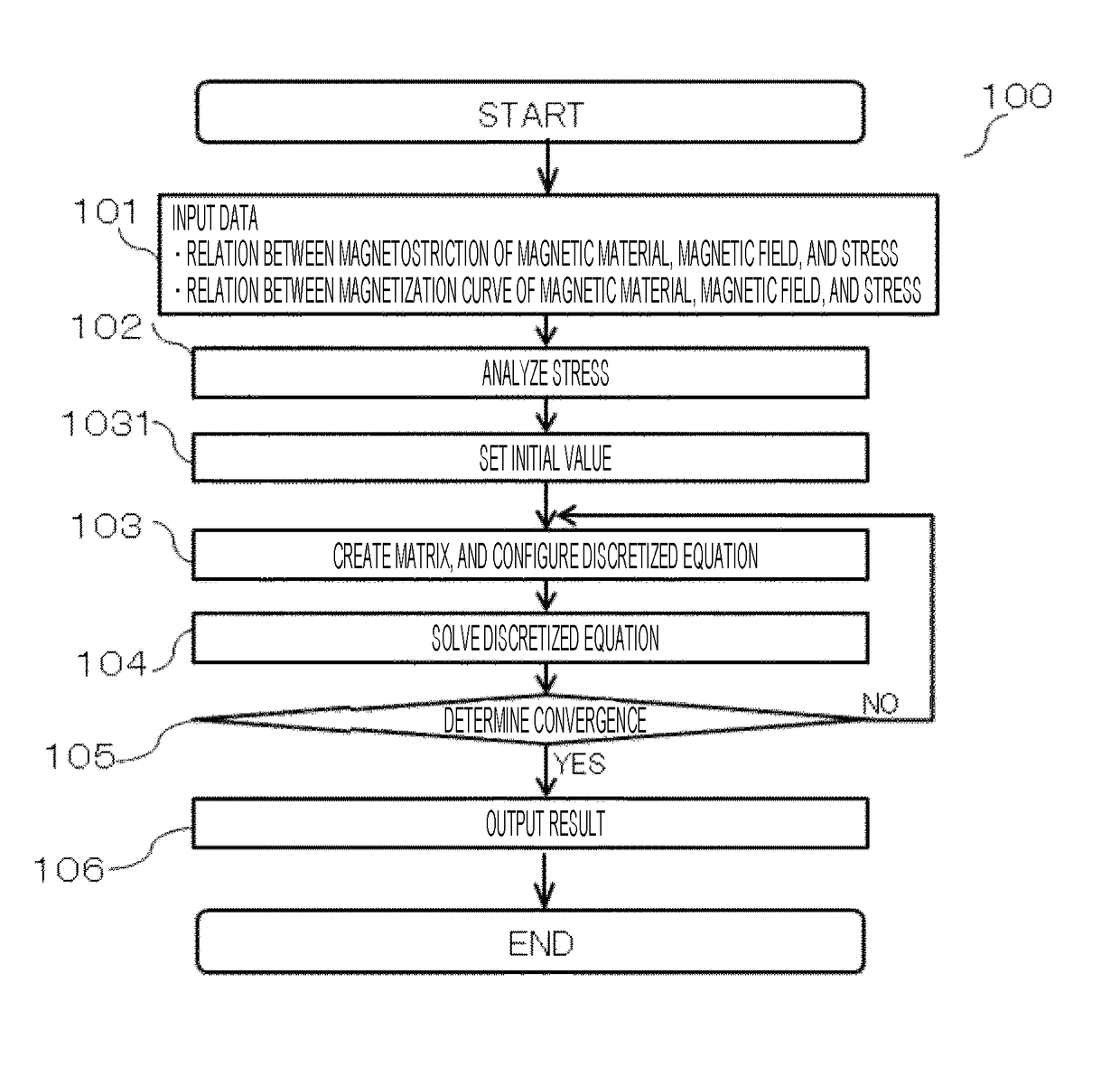
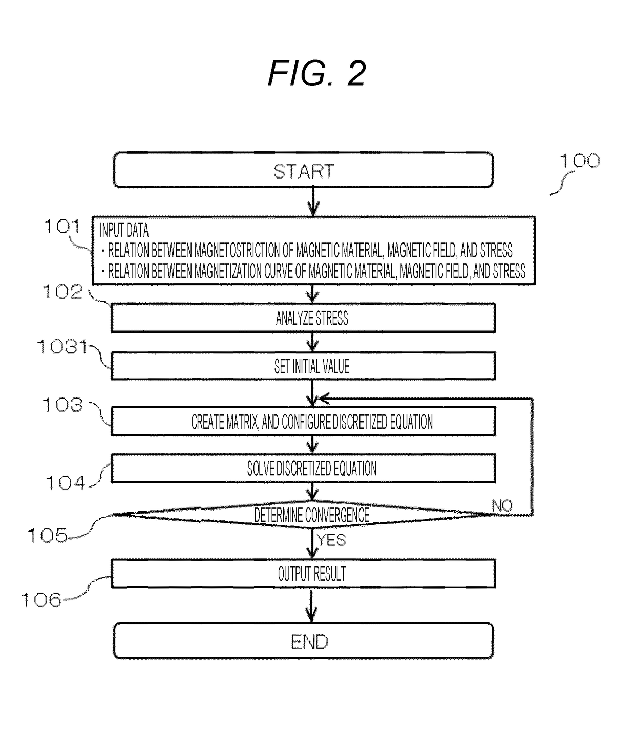
[0043]FIG. 2 is a diagram illustrating a flow of the magnetic field calculation according to this embodiment.

[0044]A flow 100 of the magnetic field calculation includes a data input portion 101, a stress analysis portion 102, an initial value setting portion 1031, a configuration portion 103 of matrix creating and discretized equation, a solving portion 104 of discretized equation, a convergence determining portion 105, and a result output portion 106.

[0045]In the data input portion 101, a relation between the magnetostriction of the magnetic material, the magnetic flux density, and the stress and a relation between the magnetization curve of the magnetic material, the magnetic flux density, and the stress which are measured on a condition that the stress and the magnetic field are parallel are input from the input device 3 in a formation such as measurement numerical data and function parameter data. Alternatively, a data file previously input to the storage device 4 is used.

[0046]...


PUM

PropertyMeasurementUnit
magnetic field analysis calculationaaaaaaaaaa
stress magnetic anisotropyaaaaaaaaaa
magnetostrictionaaaaaaaaaa

Abstract

In a magnetic field analysis calculation, there is a need to consider a characteristic that a magnetic field and a flux density face in different directions from each other by a stress in a magnetic material. Therefore, a measured value of a magnetic characteristic on a condition that the magnetic field, the magnetic flux density, and a mechanical stress are parallel is used. In a method and a device for magnetic field analysis calculation, a stress magnetic anisotropy is calculated using a relation between a magnetostriction of the magnetic material, the magnetic flux density, and the stress and a relation between a magnetization curve of the magnetic material, the magnetic flux density, and the stress which are measured on a condition that the magnetic field and the stress in the magnetic material are parallel.

Description

TECHNICAL FIELD[0001]The invention relates to a magnetic field analysis calculation method, a magnetic circuit calculation model program using the magnetic field analysis calculation method, and a recording medium with the program.BACKGROUND ART[0002]In a permanent magnet rotary machine, a torque called a cogging torque varies due to a mutual interaction between a permanent magnet and a stator core. In addition, a loss called an iron loss occurs in a core at the time of rotation. The cogging torque and the iron loss are evaluated by analyzing and calculating the magnetic field except a test after the rotary machine is manufactured.[0003]On the other hand, when the core is manufactured, generally an electromagnetic steel sheet is molded by punching, and the stator is held in the case by generating pressure between the case and the stator. In a small motor for vehicles used in an electric power steering device, the cogging torque and the iron loss are influenced by the manufacturing m...

Claims


Application Information

Patent Timeline
Patent Type & Authority Applications(United States)
IPC IPC(8): G01R33/02G01R33/12G01R33/00G06F17/50G01N27/72
CPCG01R33/02G01R33/1215G01R33/0064G06F17/5018G01N27/72G06F2217/16G01R33/18G06F30/00G06F30/20G06F2111/10G06F30/23
Inventor TAGO, KAZUTAMIMIYATA, KENJINAKANO, TOMOHITO
Owner HITACHI LTD
Learn More