System and method for local surface treatment

a local surface treatment and industrial technology, applied in the direction of electrolytic coatings, surface reaction electrolytic coatings, coatings, etc., can solve the problems of substantially equal speed, cost and energy consumption of the local surface treatment system, and achieve the effects of reducing the risk and effect of corrosion, facilitating the subsequent application of another treatment product, and improving chemical and mechanical resistance to environmental conditions

Inactive Publication Date: 2018-07-12
STELIA AEROSPACE
View PDF4 Cites 2 Cited by
  • Summary
  • Abstract
  • Description
  • Claims
  • Application Information

AI Technical Summary

Benefits of technology

[0023]The treatment products used are for example products that make it possible to limit the risks and effects of corrosion, to facilitate the subsequent application of another treatment product, to provide aesthetic quality to the part to be treated, to improve the chemical and mechanical resistance to environmental conditions, etc.
[0024]The use of a bath enclosure further makes it possible to carry out local treatment on parts of any size, in particular for example directly on an aircraft on a maintenance or repair site, without having to isolate the part to be treated. The shape of the bath enclosure can be adapted for the treatment of parts to be treated of various shapes, for example planar, curved or cylindrical (in particular for pipework).

Problems solved by technology

Furthermore, the speed, cost and energy consumption of the local surface treatment system are substantially equivalent to the bath dipping of the prior art.

Method used


Image

  • System and method for local surface treatment
  • System and method for local surface treatment
  • System and method for local surface treatment

Examples


first embodiment

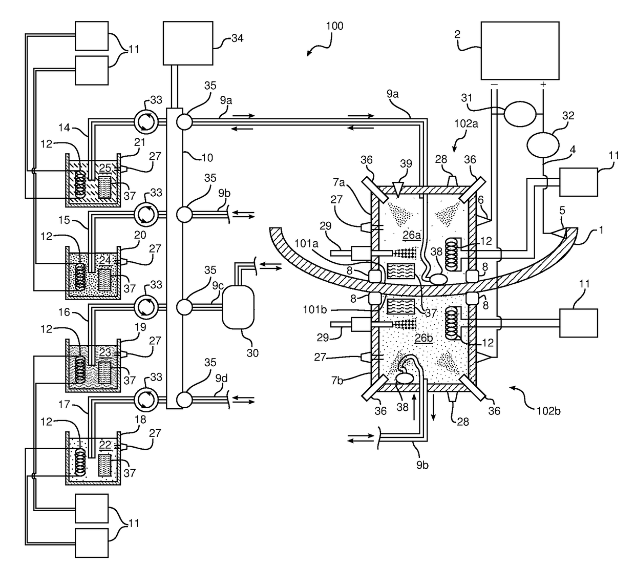
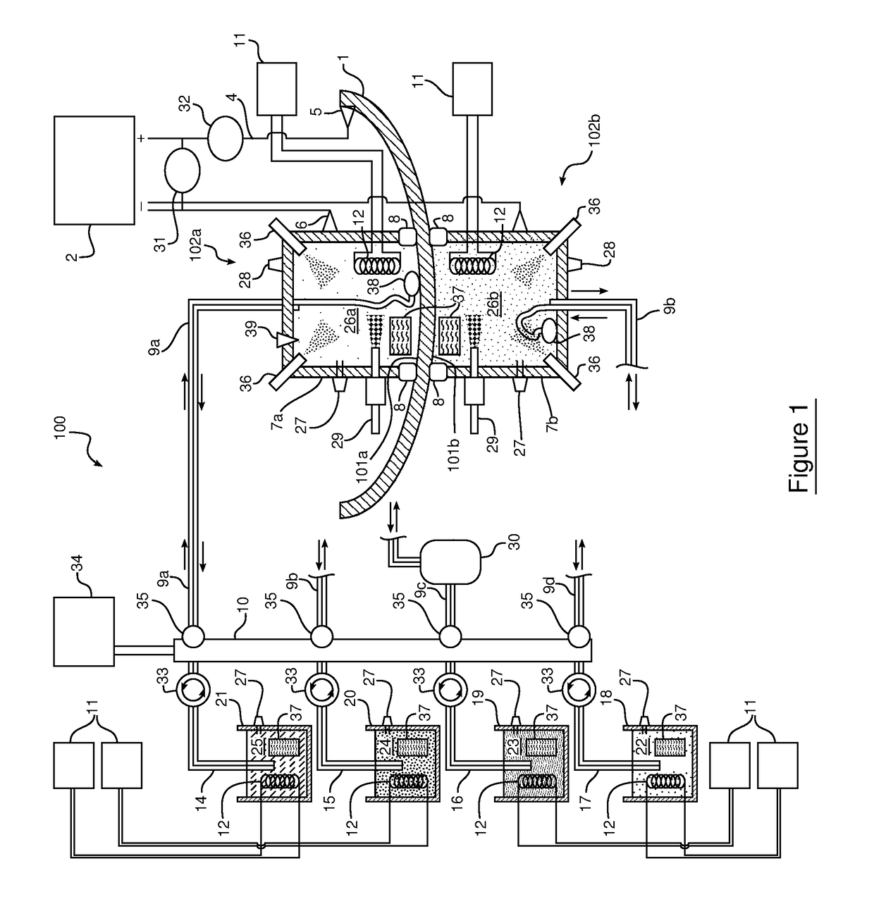
[0055]FIG. 1 depicts schematically in cross section a system 100 for the local surface treatment of a portion 101a, 101b of a part 1 to be treated according to the invention.

[0056]The system 100 makes it possible to treat a part 1 to be treated by means of treatment products 22, 23, 24, 25, each treatment product 22, 23, 24, 25 being respectively stored in a container 18, 19, 20, 21. The part 1 to be treated is, for example, a metal part forming part of an aircraft.

[0057]To carry out local treatment of the part 1 to be treated, for example on one or more portions 101a, 101b of the part to be treated, the local treatment system 100 comprises one or more bath enclosures, for example two bath enclosures 102a, 102b in this first embodiment, each being located on a face of the part 1 to be treated. Each bath enclosure 102a, 102b delimits a fluid-tight space 26a, 26b between walls 7a, 7b of each bath enclosure 102a, 102b and the portion 101a, 101b of the part to be treated. Each bath encl...
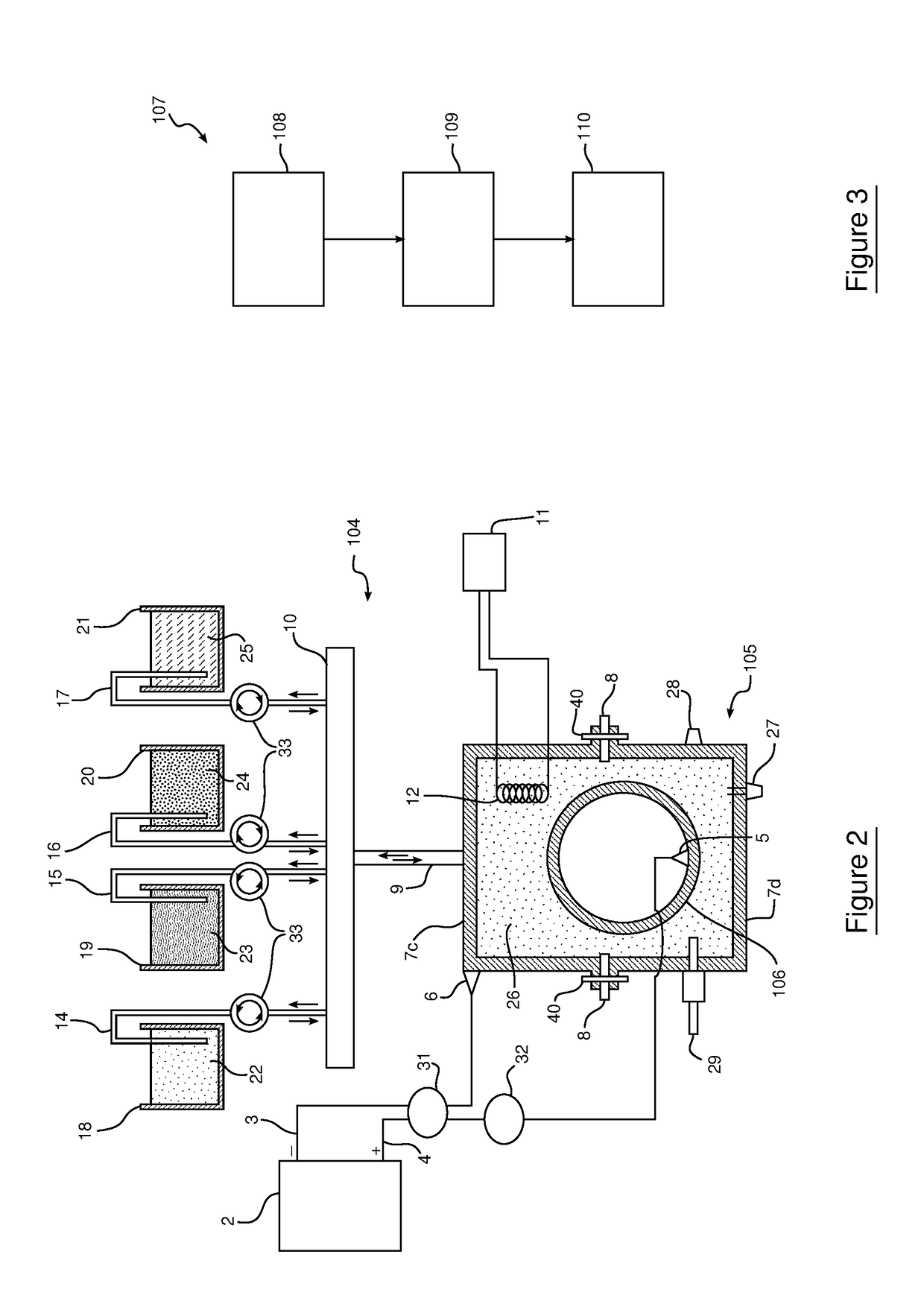
second embodiment

[0077]In this second embodiment, a single bath enclosure 105 is shown for treating a cylindrical part 106 to be treated, for example a pipe element. The part 106 to be treated is surrounded by the bath enclosure 105, and the bath enclosure 105 comprises a wall formed by portions 7c and 7d, joined by seals 8, for example electromagnetic suckers. The fixing of the two portions 7c, 7d of the wall is also reinforced by the addition of mounting flanges 40. The cylindrical part 106 to be treated is inserted in the bath enclosure through a circular opening having the same diameter as the cylindrical part 106 to be treated (not visible in the cross-sectional view). For reasons of legibility in the cross section shown in FIG. 2, the point 5 of connection to the part is shown inside the part, but the point 5 of connection to the part is advantageously located on a portion of the part that is not surrounded by the bath enclosure 105. The connection point 5 may also be located on a metal suppor...


PUM

PropertyMeasurementUnit
temperatureaaaaaaaaaa
corrosionaaaaaaaaaa
chemical resistanceaaaaaaaaaa

Abstract

The invention relates to a system for the local surface treatment of an aeronautical part (1) to be treated.
Said system is characterised in that it comprises a plurality of containers (18, 19, 20, 21) each comprising a treatment product (22, 23, 24, 25), at least one bath enclosure (102a, 102b) suitable for delimiting a fluid-tight space (26a, 26b) between this bath enclosure (102a, 102b) and a portion (101a, 101b) of the part to be treated, and a controlled circuit (10) for supplying said fluid-tight space (26a, 26b) with treatment product (22, 23, 24, 25) the containers (18, 19, 20, 21) connecting at least this container (18, 19, 20, 21) to said fluid-tight space (26a, 26b) and comprising valves for managing the supply to the fluid-tight space by one or more containers from the plurality of containers.

Description

1. TECHNICAL FIELD OF THE INVENTION[0001]The invention relates to systems and to methods for the local surface treatment of industrial parts. In particular, the invention relates to systems and to methods for the local treatment of metal parts intended for aeronautical use.2. TECHNOLOGICAL BACKGROUND[0002]The treatment of surfaces of parts, in particular metal parts, consists of applying, to the surface of a part, one or more treatment products in order to form a coating, of which the objective is improving the protection of the part, for example against corrosion, better chemical resistance or mechanical strength, etc., or a modification to the external appearance of the part, for example by applying a coat of paint.[0003]Generally, the coating is formed by applying the treatment products to the part by dipping said part in one of more baths each comprising a treatment product. The baths are located in vessels suited to the size of the part to be treated. This dipping method is alr...

Claims


Application Information

Patent Timeline
Patent Type & Authority Applications(United States)
IPC IPC(8): C25D5/02C23G3/00C25D5/34C25D21/12
CPCC25D5/026C23G3/00C25D5/34C25D21/12B05C3/005B05C3/04B05C3/109B05C3/12B05C9/04B05D1/18B05D1/32B05D2202/00C23F1/08C25D17/02C25D21/02C25D21/06C25D21/10C25D11/022C25D11/005C25D17/00B05C3/20
Inventor RIVES, BERTRAND
Owner STELIA AEROSPACE
Why Eureka
Try Eureka