Optical image capturing system

Active Publication Date: 2018-07-12
ABILITY OPTO ELECTRONICS TECH
View PDF1 Cites 12 Cited by
  • Summary
  • Abstract
  • Description
  • Claims
  • Application Information

AI Technical Summary

Benefits of technology

[0005]The aspect of embodiment of the present disclosure directs to an optical image capturing system and an optical image capturing lens which use combination of refractive powers, convex and concave surfaces of seven-piece optical lenses (the convex or concave surface in the disclosure denote

Problems solved by technology

Nevertheless, the elements of the ICR occupy a significant amount of space and are expensive,

Method used


Image

  • Optical image capturing system
  • Optical image capturing system
  • Optical image capturing system

Examples


Example

First Embodiment

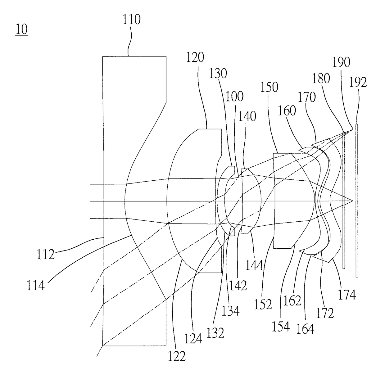
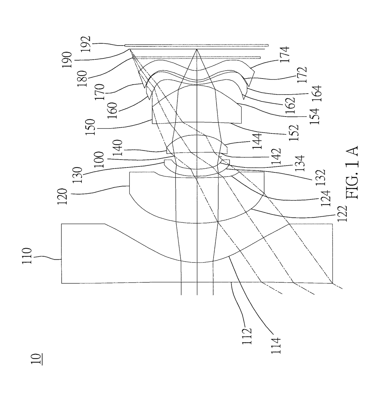
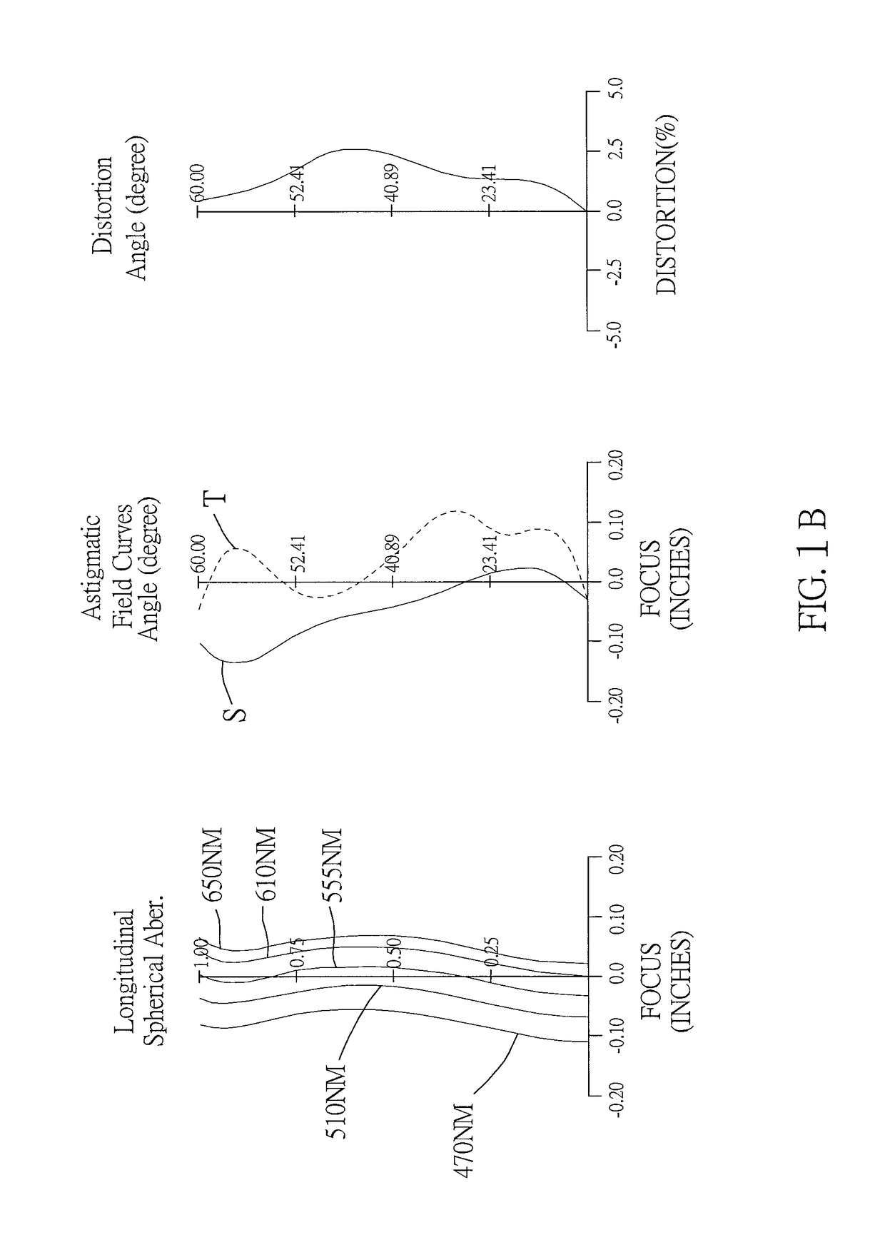
[0123]As shown in FIG. 1A and FIG. 1B, an optical image capturing system 10 of the first embodiment of the present invention includes, along an optical axis from an object side to an image side, a first lens 110, an aperture 100, a second lens 120, a third lens 130, a fourth lens 140, a fifth lens 150, a sixth lens 160, a seventh lens 170, an infrared rays filter 180, an image plane 190, and an image sensor 192. FIG. 1C shows a feature map of modulation transformation of the optical image capturing system of the first embodiment of the present application in visible light spectrum. FIG. 1D is a diagram showing the through-focus MTF values of the visible light spectrum at the central field of view, 0.3 field of view, and 0.7 field of view of the first embodiment of the present invention. FIG. 1E is a diagram showing the through-focus MTF values of the infrared light spectrum at the central field of view, 0.3 field of view, and 0.7 field of view of the first embodiment...

Example

Second Embodiment

[0191]As shown in FIG. 2A and FIG. 2B, an optical image capturing system 20 of the second embodiment of the present invention includes, along an optical axis from an object side to an image side, a first lens 210, a second lens 220, a third lens 230, an aperture 200, a fourth lens 240, a fifth lens 250, a sixth lens 260, a seventh lens 270, an infrared rays filter 280, an image plane 290, and an image sensor 292. FIG. 2C shows a feature map of modulation transformation of the optical image capturing system of the second embodiment of the present application in visible light spectrum. FIG. 2D is a diagram showing the through-focus MTF values of the visible light spectrum at the central field of view, 0.3 field of view, and 0.7 field of view of the second embodiment of the present invention. FIG. 2E is a diagram showing the through-focus MTF values of the infrared light spectrum at the central field of view, 0.3 field of view, and 0.7 field of view of the second embod...

Example

Third Embodiment

[0204]As shown in FIG. 3A and FIG. 3B, an optical image capturing system of the third embodiment of the present invention includes, along an optical axis from an object side to an image side, a first lens 310, a second lens 320, an aperture 300, a third lens 330, a fourth lens 340, a fifth lens 350, a sixth lens 360, a seventh lens 370, an infrared rays filter 380, an image plane 390, and an image sensor 392. FIG. 3C shows a feature map of modulation transformation of the optical image capturing system of the third embodiment of the present application in visible light spectrum. FIG. 3D is a diagram showing the through-focus MTF values of the visible light spectrum at the central field of view, 0.3 field of view, and 0.7 field of view of the third embodiment of the present invention. FIG. 3E is a diagram showing the through-focus MTF values of the infrared light spectrum at the central field of view, 0.3 field of view, and 0.7 field of view of the third embodiment of...


PUM


Abstract

An optical image capturing system includes, along the optical axis in order from an object side to an image side, a first lens, a second lens, a third lens, a fourth lens, a fifth lens, a sixth lens, and a seventh lens. At least one lens among the first to the sixth lenses has positive refractive force. The seventh lens can have negative refractive force, and both surfaces thereof are aspheric. At least a surface of the seventh lens has an inflection point. The lenses in the optical image capturing system which have refractive power include the first to the seventh lenses. The optical image capturing system can increase aperture value and improve the imaging quality for use in compact cameras.

Description

BACKGROUND OF THE INVENTION1. Technical Field[0001]The present invention relates generally to an optical system, and more particularly to a compact optical image capturing system for an electronic device.2. Description of Related Art[0002]In recent years, with the rise of portable electronic devices having camera functionalities, the demand for an optical image capturing system is raised gradually. The image sensing device of the ordinary photographing camera is commonly selected from charge coupled device (CCD) or complementary metal-oxide semiconductor sensor (CMOS Sensor). In addition, as advanced semiconductor manufacturing technology enables the minimization of the pixel size of the image sensing device, the development of the optical image capturing system towards the field of high pixels. Therefore, the requirement for high imaging quality is rapidly raised.[0003]The conventional optical system of the portable electronic device usually has five or six lenses. However, the opt...

Claims


Application Information

Patent Timeline
IPC IPC(8): G02B13/00G02B5/20G02B9/64
CPCG02B13/0045G02B9/64G02B5/20G02B13/18G02B5/208G02B13/008G02B13/06G02B13/14
Inventor CHANG, YEONG-MINGLAI, CHIEN-HSUNTANG, NAI-YUANLIU, YAO-WEI
Owner ABILITY OPTO ELECTRONICS TECH
Why Eureka
Try Eureka