
Package delivery by means of an automated multi-copter uas/uav dispatched from a conventional delivery vehicle

a multi-copter, conventional delivery technology, applied in vehicle position/course/altitude control, process and machine control, instruments, etc., can solve the problem of significant amount of fuel used by the delivery vehicle, and achieve the effect of reducing operating costs, reducing fuel consumption, and reducing fuel consumption

Active Publication Date: 2018-07-12
WORKHORSE GRP INC
View PDF2 Cites 30 Cited by
  • Summary
  • Abstract
  • Description
  • Claims
  • Application Information

AI Technical Summary

Benefits of technology

This patent describes a system and method for delivering packages using drones and delivery vehicles. The system reduces the distance a delivery vehicle needs to travel, resulting in lower fuel costs and lower operating costs compared to conventional methods. The delivery vehicles are not always used for deliveries, but when they are, a single drone or multiple drones can be dispatched to complete the deliveries, while the delivery vehicle remains stationary or moves to another area. This invention allows for remote areas or longer distances to be covered without moving the delivery vehicle. The system also allows for more complex delivery schedules and eliminates significant empty drive-time from a single courier's day. Overall, this invention provides a cost-effective and efficient way to deliver packages to remote areas or for other goods that cannot be reached by conventional methods.

Problems solved by technology

One major drawback of such a delivery system is the significant amount of fuel utilized by the delivery vehicle because it is required to physically travel to and from each delivery site, irrespective if there are multiple packages or just a single package to be delivered there and irrespective of the proximity of each delivery site relative to other delivery sites.

Method used


Image

  • Package delivery by means of an automated multi-copter uas/uav dispatched from a conventional delivery vehicle
  • Package delivery by means of an automated multi-copter uas/uav dispatched from a conventional delivery vehicle
  • Package delivery by means of an automated multi-copter uas/uav dispatched from a conventional delivery vehicle

Examples


Embodiment Construction

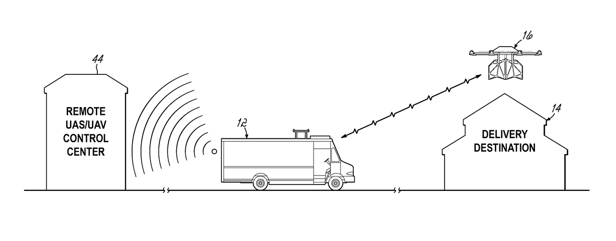
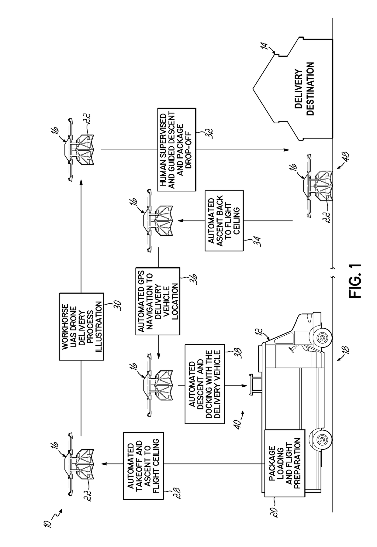
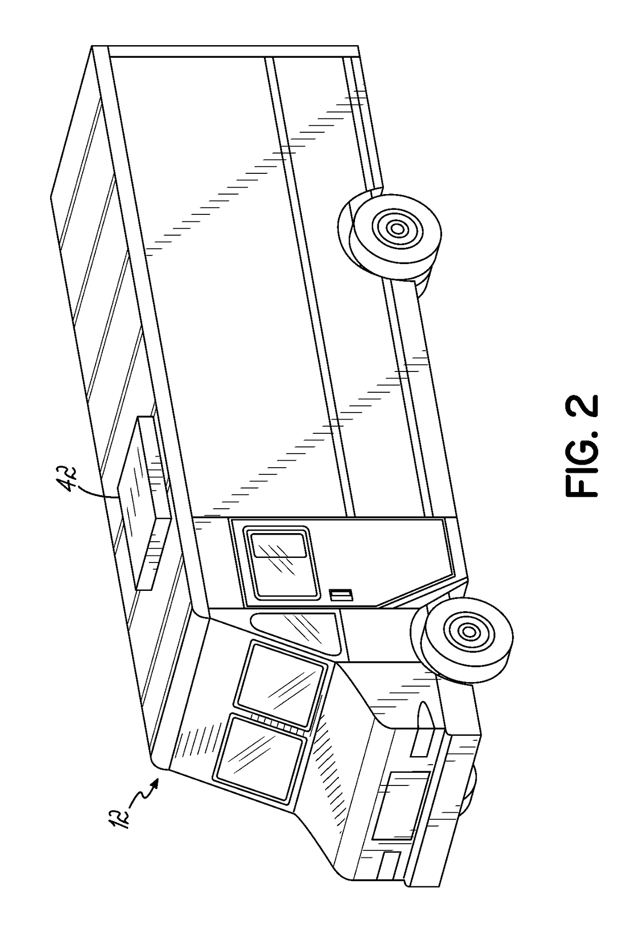
[0027]This invention will be described more fully hereafter with reference to the accompanying drawings, in which various embodiments of the invention will be described, but it is understood that other components of equal functionality may be substituted for the embodiments described herein. A package delivery system 10 includes a delivery vehicle 12 which departs from a central depot (not shown), traverses to a general delivery area, deploys packages throughout the designated area making one or more stops, 150 stops are not uncommon. On many routes there are outliers, delivery destinations 14 that are not neatly clustered in proximity to the delivery vehicle 12, hence the delivery vehicle in prior systems must traverse a greater distance to service these locations using more fuel and resulting in greater maintenance of the delivery vehicle. This invention greatly reduces fuel consumption and delivery vehicle maintenance cost by deploying one or more UAS / UAV's 16 from the delivery v...


PUM


Abstract

Methods and associated systems for autonomous package delivery utilize a UAS / UAV, an infrared positioning senor, and a docking station integrated with a package delivery vehicle. The UAS / UAV accepts a package for delivery from the docking station on the delivery vehicle and uploads the delivery destination. The UAS / UAV autonomously launches from its docked position on the delivery vehicle. The UAS / UAV autonomously flies to the delivery destination by means of GPS navigation. The UAS / UAV is guided in final delivery by means of a human supervised live video feed from the UAS / UAV. The UAS / UAV is assisted in the descent and delivery of the parcel by precision sensors and if necessary by means of remote human control. The UAS / UAV autonomously returns to the delivery vehicle by means of GPS navigation and precision sensors. The UAS / UAV autonomously docks with the delivery vehicle for recharging and preparation for the next delivery sequence.

Description

CROSS REFERENCE TO RELATED APPLICATION[0001]This is a continuation of U.S. patent application Ser. No. 14 / 989,870, filed Jan. 7, 2016 which claimed the benefit of U.S. Provisional Patent Application Ser. No. 62 / 101,542, filed on Jan. 9, 2015. Each of these prior applications is hereby incorporated by reference in its entirety.BACKGROUND OF THE INVENTION[0002]This invention relates to systems and associated methods of package delivery.[0003]Present day package delivery systems utilize a delivery vehicle, typically (but not limited to) a step van manufactured by any number of suppliers, that originates a daily delivery route from a depot, traverses a typical geographical route throughout the day, and returns to the same depot at the end of the day's delivery cycle. One major drawback of such a delivery system is the significant amount of fuel utilized by the delivery vehicle because it is required to physically travel to and from each delivery site, irrespective if there are multiple ...

Claims


Application Information

Patent Timeline
Patent Type & Authority Applications(United States)
IPC IPC(8): G05D1/10B64C39/02
CPCY02T90/162Y02T90/16Y02T10/7291Y02T90/14B64C2201/027B60L2200/10B60L2240/622G05D1/102B64C39/024B60L11/1809B64C2201/042B64C2201/128B64C2201/141B64C2201/208B60L2200/36Y02T10/7072B60L53/00B60L53/53Y02T10/72Y02T50/80Y02T10/70Y02T90/12B64U2201/10B64U80/86B64U70/93B64U10/16B64U70/97B64U80/25B64U2101/64B64F1/362B64U10/13B64U50/19B64U70/00B64U2101/60B64U50/15
Inventor BOKENO, ELLIOT T.BORT, JR., THADDEUS M.BURNS, STEPHEN S.RUCIDLO, MARTINWEI, WEIWIRES, DONALD L.
Owner WORKHORSE GRP INC
Learn More