Liquid immersion cooling system

a cooling system and liquid immersion technology, applied in the direction of electrical apparatus construction details, hoisting equipment, instruments, etc., can solve the problems of extremely difficult maintenance (specifically, adjustment, inspection, repair, replacement, etc., to prevent interference and safe lifting or lowering of electronic devices

Active Publication Date: 2018-07-12
EXASCALER
View PDF0 Cites 13 Cited by
  • Summary
  • Abstract
  • Description
  • Claims
  • Application Information

AI Technical Summary

Benefits of technology

[0023]The liquid immersion cooling system according to the present invention is configured to provide a plurality of inner partitions inside the cooling tank having an open space defined by the bottom wall and the side walls so as to divide the open space into a plurality of arrayed housing parts. The vertically long electronic devices each having the width smaller than the longitudinal length or the lateral width of the open space of the cooling tank (for example, the width approximately ½, ⅓, ¼ of those of conventional electronic devices) are highly densely housed in the respective housing parts. Those electronic devices are cooled with the cooling liquid flowing through the housing parts.
[0024]The liquid immersion cooling system according to the present invention employs the lifting mechanism equipped with the arm for lifting the vertically long electronic device from the housing part, and lowering the electronic device into the housing part. Specifically, the lifting mechanism includes a tower having a guide and a driving source for raising and lowering the arm, a slide mechanism which is attached to the cooling tank, and configured to movably support the tower at the cooling tank in a horizontal plane located above the open space, and a stopper which restricts the movement of the tower so that its movable range in the width direction of the cooling tank does not substantially exceed at least the width of the open space. The thus structured liquid immersion cooling system according to the present invention is capable of safely lifting or lowering the electronic devices highly densely housed in the cooling tank without requiring the stage in the periphery of the installation surface of the cooling tank. Additionally, it is possible to prevent interference between the operation ranges of the lifting mechanisms of the adjacent liquid immersion cooling systems.
[0025]Incidentally, the cooling tank having the “open space” in the present description is to be construed also to encompass a cooling tank having a simple sealed structure of the degree that does not spoil the maintainability of the electronic device. For example, a structure in which the top board is attached through a gasket and the like to be detachable or to be openable and closable can be regarded as the simple sealed structure.
[0026]The foregoing object and advantages and other objects and advantages of the present invention will be further clarified by the description of the following embodiments. However, the embodiments described hereafter are for exemplification purpose and do not intend to limit the present invention to the embodiments.

Problems solved by technology

However, because the synthetic oil being high in viscosity is used as the cooling liquid, it is difficult to completely remove, from electronic devices taken out from oil-immersed racks, the oil adhered thereto, and this gives rise to a problem that the maintenance (specifically, adjustment, inspection, repair, replacement and expansion, for example; the same applies hereafter) of the electronic devices is extremely difficult.
Furthermore, the occurrence of a problem has also been reported that causes a difficulty to arise in practical use because the synthetic oil in use leaks by corroding a gasket and the like constituting the cooling system in a short period of time.

Method used


Image

  • Liquid immersion cooling system
  • Liquid immersion cooling system
  • Liquid immersion cooling system

Examples


Embodiment Construction

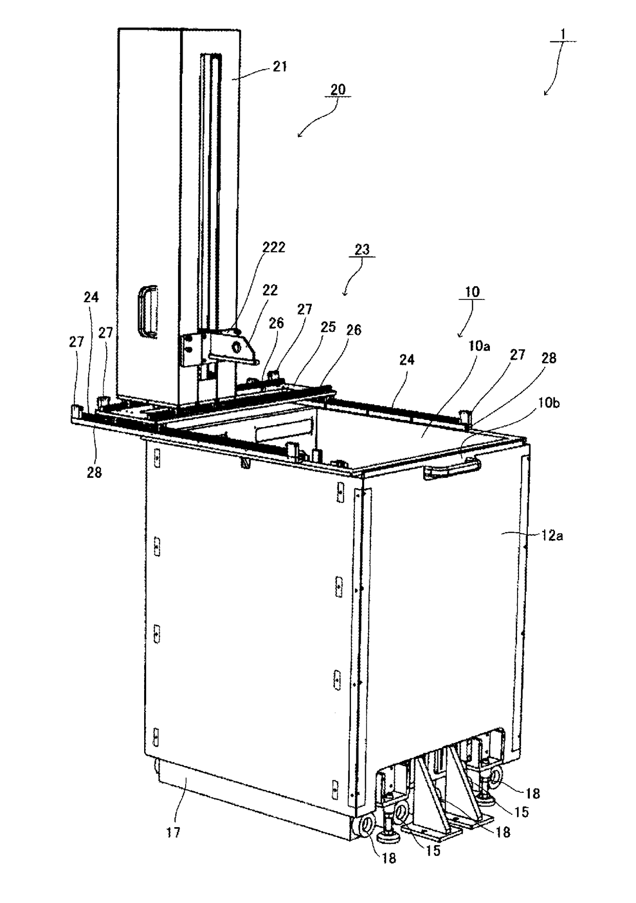
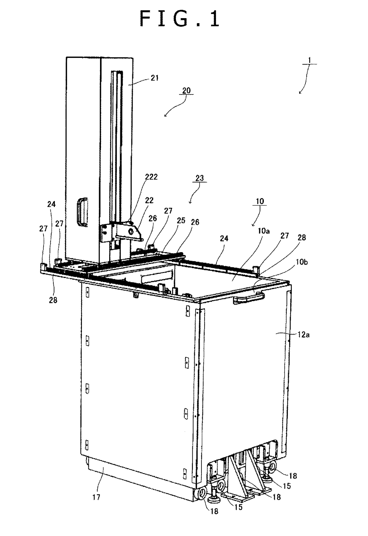
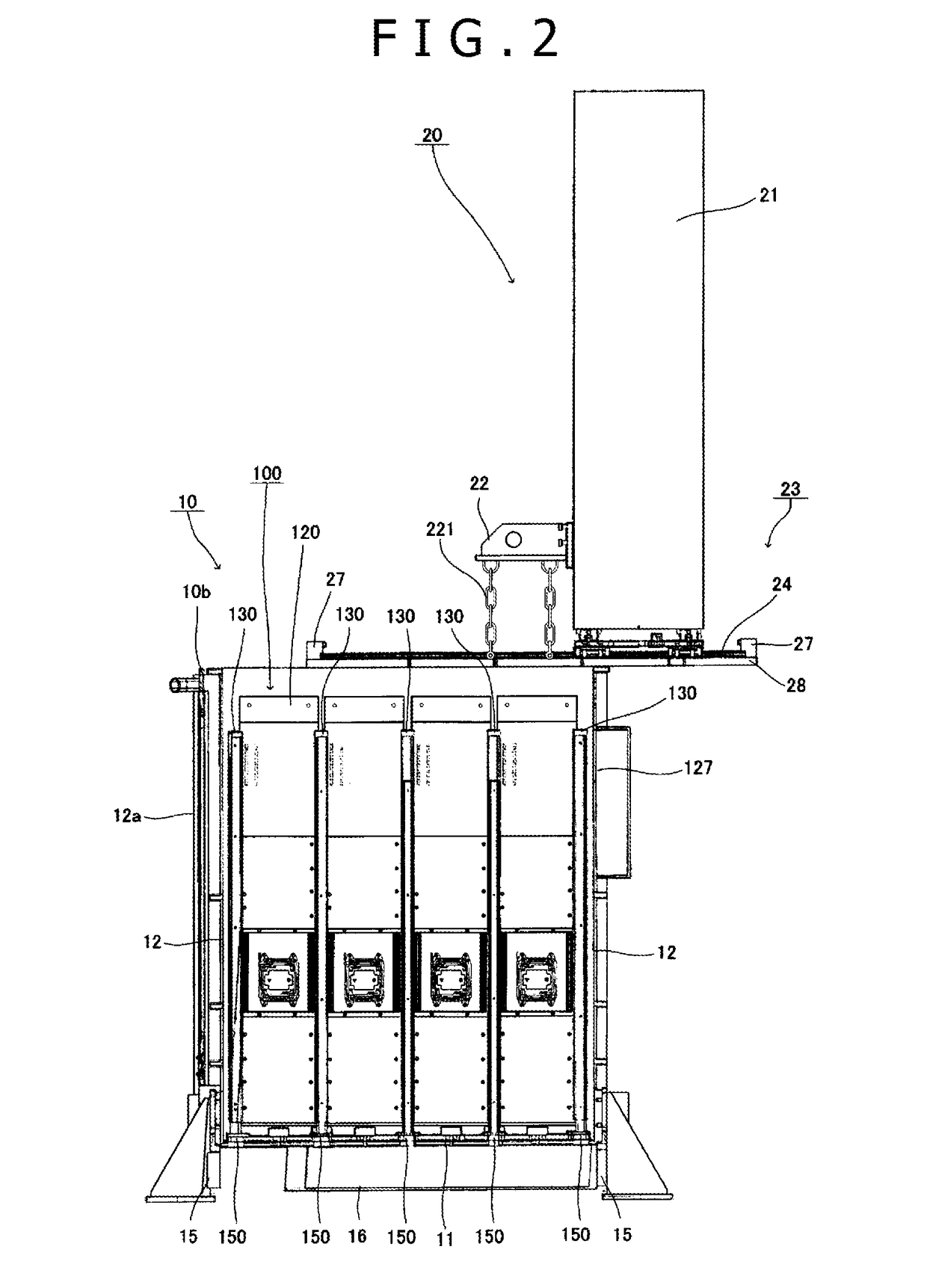
[0033]A preferred embodiment of the liquid immersion cooling system according to the present invention will be described in detail referring to the drawings. In the description, a plurality of processor boards each having a processor formed of a CPU or a GPU installed therein are disposed on both surfaces of the board to constitute an electronic device (1 unit). An explanation will be made with respect to the high density liquid immersion cooling system configured to house 16 units of the electronic device in the divided housing parts of the cooling tank so as to be cooled. Incidentally, these are for the purpose of exemplifications. The number of units of the electronic device housed in the highly densified liquid immersion cooling system is discretionary. They do not limit in anyway the configuration of the electronic device to which the present invention is applied.

[0034]Referring to FIG. 1 to FIG. 6, a liquid immersion cooling system 1 according to an embodiment of the present i...


PUM


Abstract

Inner partitions disposed within a cooling tank have an open space to form arrayed housing parts, and at least one unit of electronic device housed in each of the housing parts. A lifting mechanism includes a tower having a guide and a driving source for raising and lowering an arm, a slide mechanism attached to the cooling tank, and a stopper for restricting the tower's movement so that a range of the tower's motion in a width direction of the cooling tank does not exceed at least a width of the open space. The slide mechanism supports the tower movably with respect to the cooling tank in a horizontal plane located above the open space. The liquid immersion cooling system can safely lift or lower the electronic devices densely housed within the cooling tank without requiring the stage in the periphery of the installation surface of the cooling tank.

Description

TECHNICAL FIELD[0001]The present invention relates to a liquid immersion cooling system for electronic device. More specifically, the present invention relates to the liquid immersion cooling system equipped with a lifting mechanism, containing cooling liquid flowing through the cooling tank for immersing and cooling the electronic device, for example, supercomputer or data center, which is configured to generate high heating value, and is required to exhibit superhigh performance and stable operation.BACKGROUND ART[0002]Conventionally, an air-cooling type and a liquid-cooling type have been in use for cooling supercomputers and data centers. The liquid-cooling type is generally recognized to be high in cooling efficiency because of using a liquid that is remarkably superior to air in heat transfer performance. For example, the liquid immersion cooling system using synthetic oil has been employed for the supercomputer called “TSUBAME-KFC” constructed by Tokyo Institute of Technology...

Claims


Application Information

Patent Timeline
Patent Type & Authority Applications(United States)
IPC IPC(8): G06F1/20H05K7/20B66D3/26
CPCG06F1/20H05K7/20236H05K7/20272B66D3/26G06F2200/201H05K7/20763H05K7/20781H01L23/44
Inventor SAITO, MOTOAKI
Owner EXASCALER
Why Eureka
Try Eureka