
Method and system for locating a network device in an emergency situation

a network device and emergency situation technology, applied in the direction of wireless communication, machine-to-machine/machine-type communication service, instruments, etc., can solve the problems of inability to meet the requirements accuracy, prior art methods of accomplishing such location, etc., to achieve the effect of rapid location determination, automation, and accuracy, and navigation using conventional maps and visual observation or dead reckoning is not readily automated

Active Publication Date: 2018-07-19
EVERBRIDGE
View PDF3 Cites 54 Cited by
  • Summary
  • Abstract
  • Description
  • Claims
  • Application Information

AI Technical Summary

Benefits of technology

The invention provides a method and system to locate a mobile network device in an emergency situation. By obtaining the current physical location information of a network device when it registers on a network or moves to a new location, and sending it in an encrypted format to an appropriate Public Safety Answering Point (PSAP) in real-time, emergency responders can be quickly dispatched to the current physical location of the network device. This helps to improve the efficiency and accuracy of emergency response operations.

Problems solved by technology

For example, in the event of a vehicular accident, public safety personnel may need to operate within an unfamiliar wooded area on short notice, in conditions of poor visibility due to smoke, flame or darkness.
A mobile device an individual may be carrying may not be able to communicate because of poor signal strength to the mobile device in the rural area.
Prior art methods of accomplishing such location do not simultaneously meet the requirements of rapid location determination, automation, and accuracy.
Navigation employing conventional maps and visual observation or dead reckoning are not readily automated and thus require time and attention by a human observer.
However, the problem with all of these methods is that they are all manual processes.
In addition, if the static location of the end point device is not updated, in the event of any emergency situation, the end point device would not provide the correct emergency location when a 9-1-1 call is made.
This endangers the health and safety of the caller.

Method used


Image

  • Method and system for locating a network device in an emergency situation
  • Method and system for locating a network device in an emergency situation
  • Method and system for locating a network device in an emergency situation

Examples


Embodiment Construction

Electronic Emergency Location Information Message Processing System

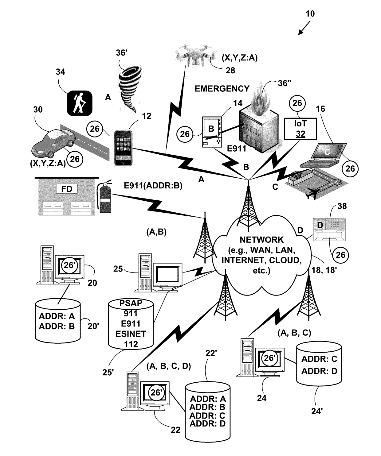
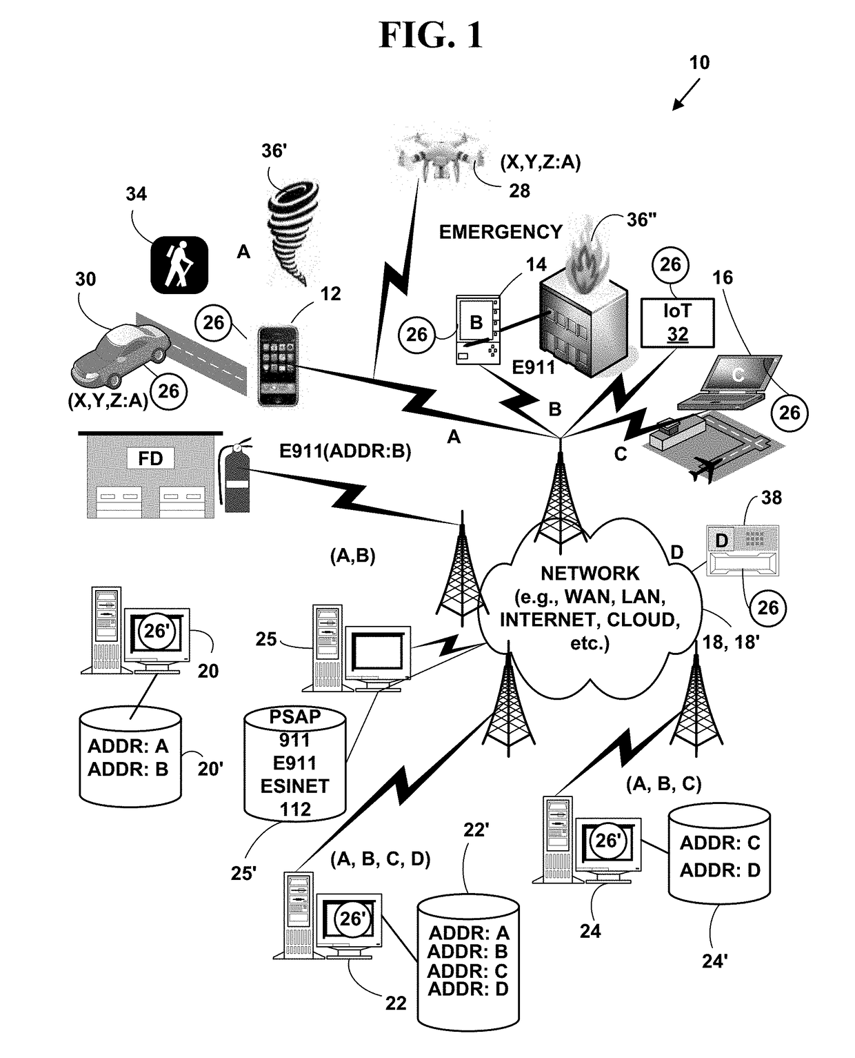
[0026]FIG. 1 is a block diagram illustrating an exemplary communications system 10. The exemplary communications system 10 includes, but is not limited to, one or more target network devices, each with one or more processors and each with a non-transitory computer readable medium. Only selected ones of the target network devices are illustrated in the drawings for simplicity.

[0027]The target network devices, include, but are not limited to, mobile phones including smart phones 12, electronic tablets 14, mobile computers 16, unmanned aerial vehicles (UAV) 28, commonly known as “drones” and also referred to as “Remotely Piloted Aircraft (RPA),” driverless vehicles 30, vehicles with a driver, Internet of Things (IoT) network devices 32, and other target network devices that determine a current physical location 34 of a target network device during an emergency event 36′, 36″, etc. (e.g., weather event 36′, fire 36″, etc...


PUM


Abstract

A method and system for locating a network device in an emergency situation. Current physical location information is obtained for a network device every time it registers on a network or moves to a new physical location. The current physical location is sent and received in an encrypted format to and from the network device. When the network device initiates an emergency message (e.g. 911, E911, NG911, text-to-911, 112, etc.) based on an emergency event (e.g., weather, crime, fire, natural disaster, medical, terrorist, military, etc.), the emergency message includes the encrypted current physical location information for the network device. The current physical location information is decrypted and the emergency message is immediately routed in real-time to an appropriate Public Safety Answering Point (PSAP). The appropriate PSAP is immediately notified in real-time so emergency responders (e.g., police, fire, medical, etc.) can be dispatched to the current physical location of the network device.

Description

CROSS REFERENCES TO RELATED APPLICATIONS[0001]This U.S. utility patent application is a Continuation-In-Part (CIP) of U.S. utility patent application Ser. No. 15 / 491,608, filed Apr. 19, 2017, which is a CIP of U.S. utility patent application Ser. No. 14 / 806,068 filed on Jul. 22, 2015, that issued into U.S. Pat. No. 9,935,534, on Apr. 25, 2017, which is a CIP of U.S. utility patent application Ser. No. 14 / 579,760, filed on Dec. 22, 2014, that issued as U.S. Pat. No. 9,094,816, on Jul. 28, 2015, which is a CIP of U.S. patent application Ser. No. 14 / 303,842, filed on Jun. 13, 2014, that issued as U.S. Pat. No. 8,918,075, on Dec. 23, 2014, which is a CIP of U.S. utility patent application Ser. No. 13 / 831,426, filed Mar. 14, 2013, which issued as U.S. Pat. No. 8,755,767, on Jun. 17, 2014, which is a CIP of U.S. utility patent application Ser. No. 13 / 098,981, filed May 2, 2011, which issued and U.S. Pat. No. 8,442,482 on May 14, 2013, which is a CIP of U.S. utility patent application Ser....

Claims


Application Information

Patent Timeline
IPC IPC(8): H04W4/90H04W4/029H04L29/06G06F17/30H04M1/72421H04M1/72457
CPCH04W4/90H04W4/029H04L63/0428H04L63/168G06F17/3087G06F17/30595H04W4/023H04W4/025H04W64/00H04W64/003H04W76/50H04W4/70H04W4/80H04W12/02G06F16/9537H04W4/02H04W4/14H04M1/72421H04M1/72457H04L67/52G06F16/284
Inventor EISNER, GERALD R.FOREHAND, JASON E.
Owner EVERBRIDGE
Learn More