Component mounting device

a technology of mounting device and component, which is applied in the direction of image analysis, image enhancement, instruments, etc., can solve the problems of disadvantageous increase in production time, and achieve the effect of accurate determination, accurate determination, and accurate determination

Active Publication Date: 2018-07-19
YAMAHA MOTOR CO LTD
View PDF4 Cites 1 Cited by
  • Summary
  • Abstract
  • Description
  • Claims
  • Application Information

AI Technical Summary

Benefits of technology

[0011]In the aforementioned component mounting device according to this aspect, the control section is preferably configured to determine whether or not the component has been successfully mounted at the mounting position by determining whether or not a predetermined amount or more of a portion having a height equal to or more than a predetermined height is included based on the information about the height of the mounting position. According to this structure, it is possible to make a success or failure determination based on a wide range of measurement results by determining whether or not a predetermined amount or more of the portion having a height equal to or more than the predetermined height is included, and hence it is possible to more accurately determine whether or not the component has been successfully mounted at the mounting position.
[0012]In the aforementioned component mounting device according to this aspect, the control section is preferably configured to control the imaging section to image the predetermined region before and after mounting of the component, to acquire the information about the height of the mounting position before and after mounting of the component based on imaging results of the predetermined region before and after mounting of the component imaged by the imaging section, and to determine whether or not the component has been successfully mounted at the mounting position based on a change in the acquired information about the height of the mounting position before and after mounting of the component. According to this structure, it is possible to make a success or failure determination for the component at the mounting position based on a change in the actual height of the mounting position (a change in the height of the mounting position due to mounting of the component). Consequently, it is possible to more accurately determine whether or not the component has been successfully mounted at the mounting position as compared with the case where a success or failure determination for the component at the mounting position is made based only on the height information after mounting of the component. This effect is particularly beneficial when it is determined whether or not a small-sized component, which is difficult to distinguish from an object such as a solder placed at the mounting position, has been successfully mounted.
[0013]The aforementioned component mounting device according to this aspect preferably further includes an image processing section that generates a difference image between an image of the mounting position before mounting of the component captured by the imaging section and an image of the mounting position after mounting of the component captured by the imaging section, and the control section is preferably configured to determine whether or not the component has been successfully mounted at the mounting position based on the generated difference image in addition to the information about the height of the mounting position. According to this structure, it is possible to make a success or failure determination for the component at the mounting position based not only on the information about the height of the mounting position but also on the generated difference image, and hence it is possible to more accurately determine whether or not the component has been successfully mounted at the mounting position.
[0014]In the aforementioned component mounting device according to this aspect, the imaging section is preferably configured to be capable of imaging the mounting position from a plurality of imaging directions, and the control section is preferably configured to control the imaging section to image the predetermined region from the plurality of imaging directions during the period from the time point at which the mounting section finishes mounting the component at the mounting position to the time point at which the mounting section completes upward movement from the mounting position, and to acquire the information about the height of the mounting position based on imaging results of the predetermined region imaged by the imaging section from the plurality of imaging directions. According to this structure, it is possible to easily acquire the information about the height of the mounting position based on the imaging results of the predetermined region imaged by the imaging section from the plurality of imaging directions.
[0015]In this case, the imaging section is preferably configured to be capable of imaging the mounting position from the plurality of imaging directions inclined with respect to the substrate surface. According to this structure, the mounting position can be imaged from the oblique directions, and hence the mounting position can easily fit within the field of view of the imaging section without moving the imaging section after mounting.
[0016]According to the present disclosure, as hereinabove described, the component mounting device capable of determining whether or not the component has been successfully mounted at the mounting position while significantly reducing or preventing an increase in the time taken for production can be provided.

Problems solved by technology

Thus, the suction head and the height sensor are moved, and hence the time taken for production is disadvantageously increased.

Method used


Image

  • Component mounting device
  • Component mounting device
  • Component mounting device

Examples


first embodiment

[0030](Structure of Component Mounting Device)

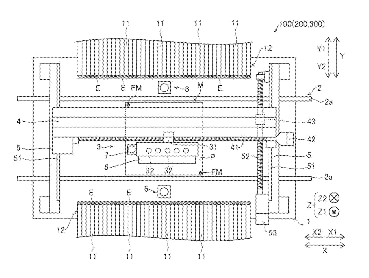
[0031]The structure of a component mounting device 100 according to a first embodiment of the present disclosure is now described with reference to FIGS. 1 to 6.

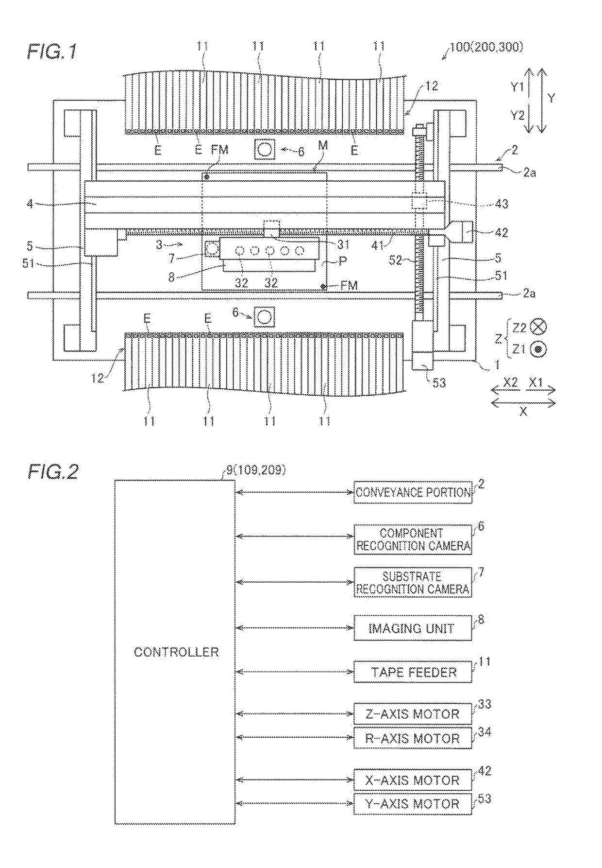
[0032]As shown in FIG. 1, the component mounting device 100 is a device that mounts components E (electronic components), such as ICs, transistors, capacitors, and resistors, on a substrate P such as a printed board. The component mounting device 100 includes a base 1, a conveyance portion 2, a head unit 3, a support 4, rails 5, component recognition cameras 6, a substrate recognition camera 7, an imaging unit 8, and a controller 9 (see FIG. 2). The imaging unit 8 is an example of an “imaging apparatus” or an “imaging section.” The controller 9 is an example of a “controller” or a “control section.”

[0033]Feeder placement portions 12 for arranging a plurality of tape feeders 11 are respectively provided on both ends (a Y1 side and a Y2 side) of the base 1 in a direction Y. The tap...

second embodiment

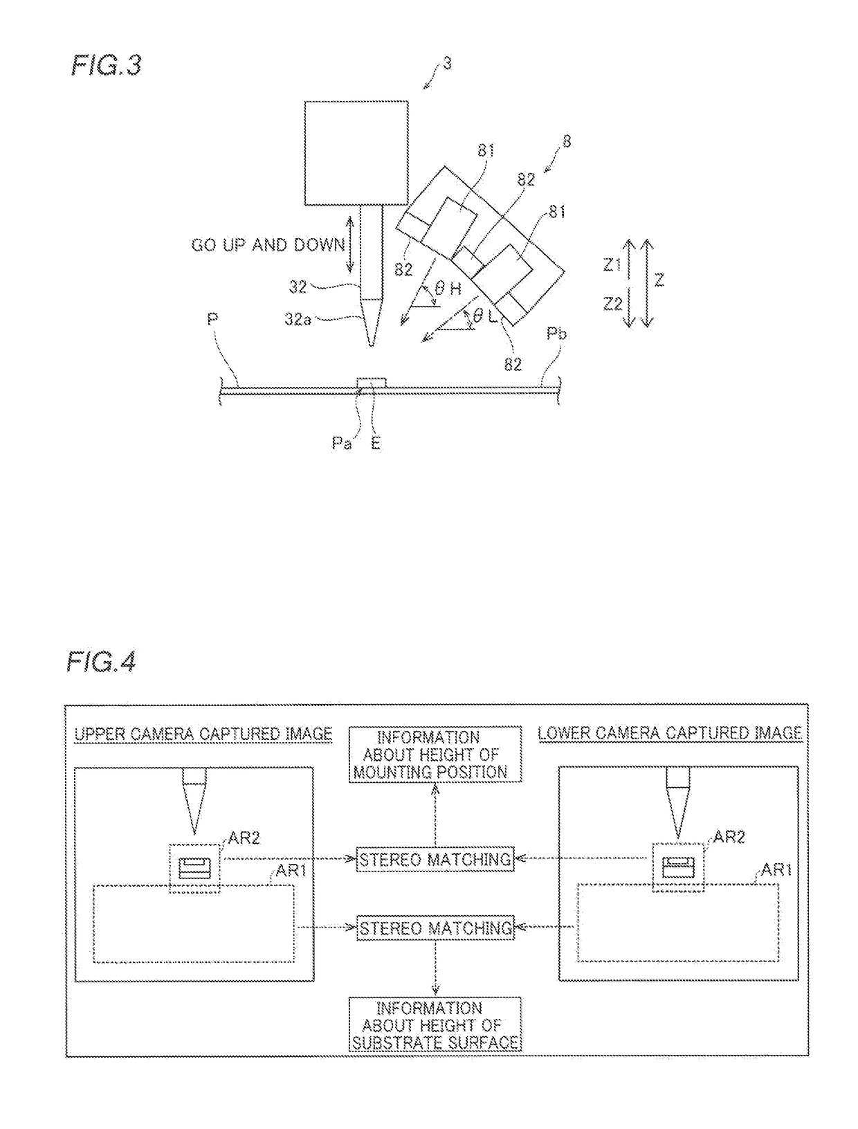
[0089]A second embodiment is now described with reference to FIGS. 1 to 4 and 8 to 10. In this second embodiment, an example in which a success or failure determination is made based on a change in height information based on imaging results of a predetermined region before and after mounting is described unlike the aforementioned first embodiment in which a success or failure determination is made based on the height information based on the imaging result of the predetermined region after mounting.

[0090](Structure of Component Mounting Device)

[0091]As shown in FIG. 2, a component mounting device 200 (see FIG. 1) according to the second embodiment of the present disclosure is different from the component mounting device 100 according to the aforementioned first embodiment in that the component mounting device 200 includes a controller 109. The controller 109 is an example of a “controller” or a “control section.” The same structures as those of the aforementioned first embodiment a...

third embodiment

[0115]A third embodiment is now described with reference to FIGS. 1 to 4 and 11. In this third embodiment, in addition to the structure of the aforementioned first embodiment or the structure of the aforementioned second embodiment, an example in which a success or failure determination is made based on a difference image between captured images before and after mounting is described.

[0116](Structure of Component Mounting Device)

[0117]As shown in FIG. 2, a component mounting device 300 (see FIG. 1) according to the third embodiment of the present disclosure is different from the component mounting device 100 according to the aforementioned first embodiment and the component mounting device 200 according to the aforementioned second embodiment in that the component mounting device 300 includes a controller 209. The controller 209 is an example of a “control section,”“a controller,” an “image processing section” or an “image processor.” The same structures as those of the aforemention...


PUM

PropertyMeasurementUnit
inclination angleaaaaaaaaaa
heightaaaaaaaaaa
imaging apparatusaaaaaaaaaa

Abstract

A component mounting device includes a controller that controls an imaging unit to image a predetermined region during a period from a time point at which a head finishes mounting a component at a mounting position to a time point at which the head completes upward movement from the mounting position, and acquires information about a height of the mounting position based on an imaging result of the predetermined region imaged by the imaging unit. The controller further determines whether or not the component has been successfully mounted at the mounting position based on the acquired information about the height of the mounting position.

Description

CROSS-REFERENCE TO RELATED APPLICATION[0001]This application is a National Stage of International Patent Application No. PCT / JP2015 / 073054, filed Aug. 17, 2015, the entire content of which is incorporated herein by reference.TECHNICAL FIELD[0002]The present disclosure relates to a component mounting device, and more particularly, it relates to a component mounting device that determines whether or not a component has been successfully mounted at a mounting position.BACKGROUND ART[0003]In general, a component mounting device that determines whether or not a component has been successfully mounted at a mounting position is known as described, for example, in Japanese Patent Laying-Open No. 2000-13097.[0004]Japanese Patent Laying-Open No. 2000-13097 discloses a component mounting device including a suction head that suctions a component and mounts the suctioned component on a substrate and a height sensor that measures the height of the component mounted on the substrate and configured...

Claims


Application Information

Patent Timeline
Patent Type & Authority Applications(United States)
IPC IPC(8): H05K13/04G06T7/00H05K13/08
CPCH05K13/0452G06T7/0004H05K13/08H05K13/0417G06T2207/30141H05K13/083H05K13/0815Y10T29/49131H05K13/0812Y10T29/53174
Inventor TAKAMA, KAZUSHINAKAMURA, SEIJI
Owner YAMAHA MOTOR CO LTD
Why Eureka
Try Eureka