Eureka AIR delivers breakthrough ideas for toughest innovation challenges, trusted by R&D personnel around the world.

Switching device

Active Publication Date: 2018-07-26
ELLENBERGER POENSGEN
View PDF14 Cites 0 Cited by
  • Summary
  • Abstract
  • Description
  • Claims
  • Application Information

AI Technical Summary

Benefits of technology

The invention is about a switching device that is easy to install and can separate contacts from adjacent devices. It is also reliable and secure, especially when releasing a device on a rail.

Problems solved by technology

This, on the one hand, increases space requirements within a switch cabinet.
On the other hand, especially in a mounting situation within a series connection of the current distributor, the problem may occur that the securing device or the actuating element coupled thereto is difficult to access or only accessible in a limited manner, so that the switching device may not be easily released from the series connection.

Method used


Image

  • Switching device
  • Switching device
  • Switching device

Examples


Embodiment Construction

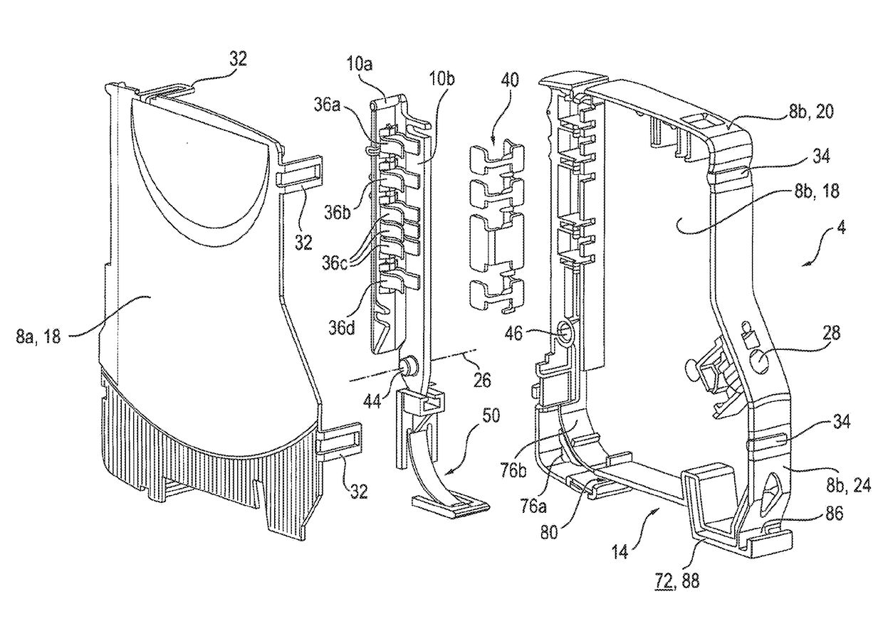
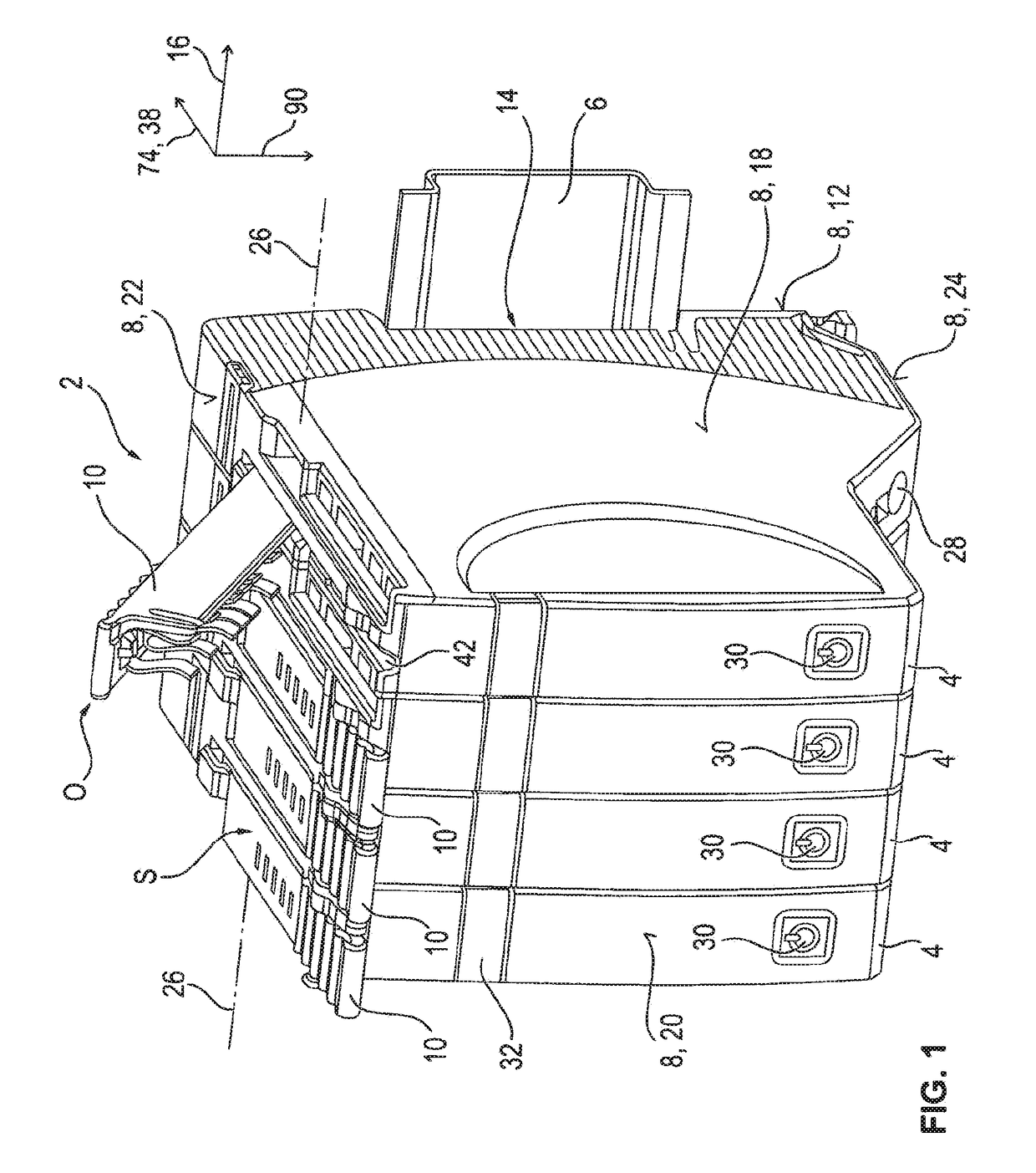
[0056]The current distributor 2 shown in FIG. 1 comprises four protective devices 4, which are arranged in series and mounted on a carrier rail 6. Each switching device 4 comprises a separate, i.e., separated from the other switching devices 4, housing 8 with a pivotable (housing) cover 10. The housing 8 and the cover 10 are preferably made of an insulating material. The switching devices 4 are designed in the manner of a rail mounted device, and accordingly have a groove-like receptacle 14 at a respective rear side of the housing 12, with which for mounting purposes the respective protective device 4 can be placed on the carrier rail 6.

[0057]The profile direction of this receptacle 14—and, accordingly, in the mounted state, the profile direction of the carrier rail 6 corresponding to this receptacle 14—define a row direction (carrier rail longitudinal direction) 16 along which the switching devices 4 are arranged in series. The housing surfaces of each switching device 4 situated o...


PUM


Abstract

A switching device having a housing, with a cover that can pivot about a rotational axis, and a securing device for carrier rail mounting. The cover has at least one coupling contact for an electrical and / or signal-type contact connection with at least one engageable switching device. A closing or releasing of the contact connection occurs with a pivoting of the cover. A locking or unlocking of the securing device occurs with a pivoting of the cover. The securing device has a spring-elastic clipping element shaped on the housing, for force-locking securing to a carrier rail end face, and has a sliding element, which is mounted such that it can slide in a linear manner within the housing and is coupled to the cover, for interlocking securing to the carrier rail end face opposite the clipping element.

Description

[0001]This nonprovisional application is a continuation of International Application No. PCT / EP2016 / 068463, which was filed on Aug. 2, 2016, and which claims priority to German Patent Application No. 10 2015 218 108.1, which was filed in Germany on Sep. 21, 2015, and which are both herein incorporated by reference.BACKGROUND OF THE INVENTIONField of the Invention[0002]The present invention relates to a switching device, in particular in the form of an electrical switching device or a rail mounted device arranged in series.Description of the Background Art[0003]An electrical switching device, such as a mechanical, electronic or mechatronic circuit breaker, typically includes a supply terminal via which a network-side and thus the current-carrying main power line can be connected, and a load terminal, to which a load-side, outgoing power line can be connected.[0004]As a switching device arrangement or current distribution system, hereinafter in particular an electrical installation is...

Claims


Application Information

Patent Timeline
IPC IPC(8): H01H71/08H01R9/26H02B1/052
CPCH01H71/082H01R9/2608H01R9/2675H02B1/0526H01R9/2633H02B1/052H02B1/205
Inventor ROTH, HERBERT
Owner ELLENBERGER POENSGEN
Why Eureka
Eureka Blog
Learn More