
Automated Lifting Floor for Underfloor Storage

a technology of lifting floor and storage floor, which is applied in the direction of adjustable height tables, adjustable cabinets, furniture parts, etc., can solve the problems of building or other structure that can take months or even years to build, building project is consequently subject to unpredictable weather conditions, and large effort must be made to store and protect tools and resources

Active Publication Date: 2018-08-02
HALL LABS LLC
View PDF7 Cites 3 Cited by
  • Summary
  • Abstract
  • Description
  • Claims
  • Application Information

AI Technical Summary

Benefits of technology

The present invention solves the problems in the current art by providing efficient structural components and methods for a modular underfloor infrastructure with space for storage. The invention is a lifting floor system comprising an underfloor support structure with partitions and frames that can be lifted by one or more lifting devices, exposing usable space between each floor piece and sub-floor piece. The frames can be used for storing anything from household appliances to household furniture. The technical effect of the invention is the creation of a versatile and flexible space-saving solution for modular underfloor infrastructure.

Problems solved by technology

When such methods are used, however, a building or other structure can take months or even years to build.
The building project is consequently subjected to unpredictable weather conditions, and great exertions must be made to store and protect tools and resources.
Additionally, even though efficient modern assembly techniques have driven down prices for many industrial and consumer products—such as cars, machinery, clothing, and electronics—such techniques are not fully taken advantage of in constructing buildings.
Overall, current methods lose the potential benefits of quality, precision, efficiency, and optimal timing that could be possible through the manufacture of modular building segments in a controlled environment.
Furthermore, current building techniques seldom lead to optimally green or sustainable structures.
However, most buildings and other structures fail to optimally utilize the space available.
For example, few buildings make use of an area of wasted space within the frame of the roof or ceiling.

Method used


Image

  • Automated Lifting Floor for Underfloor Storage
  • Automated Lifting Floor for Underfloor Storage
  • Automated Lifting Floor for Underfloor Storage

Examples


Embodiment Construction

[0021]A detailed description of the claimed invention is provided below by example, with reference to embodiments in the append.ed figures. Those of skill in the art will recognize that the components of the invention as described by example in the figures below could be arranged and designed in a wide variety of different configurations. Thus, the detailed description of the embodiments in the figures is merely representative of embodiments of the invention, and is not intended to limit the scope of the invention as claimed.

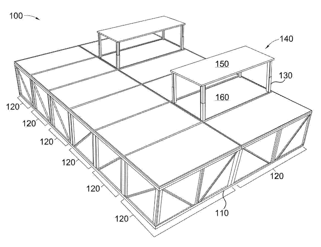
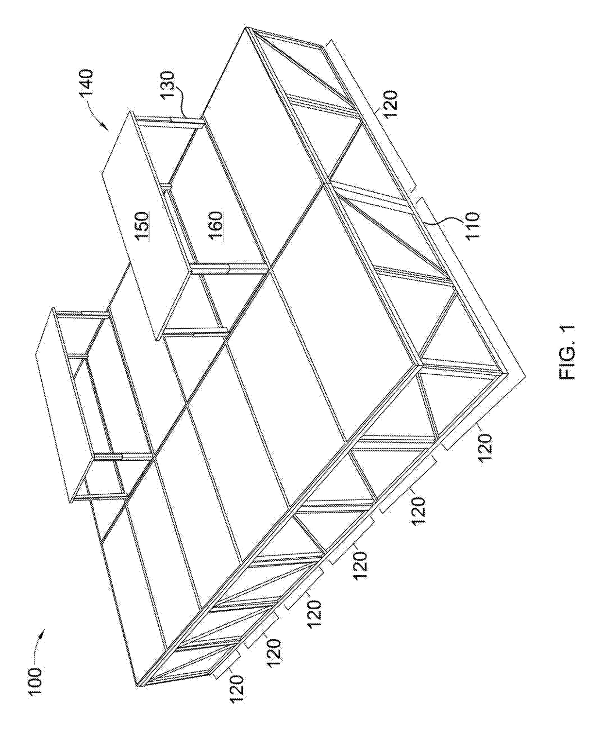
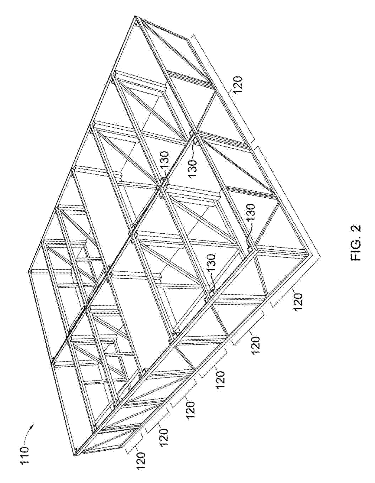
[0022]FIG. 1 depicts one embodiment of a lifting floor system 100. The lifting floor system 100 comprises an underfloor support structure 110. The underfloor support structure 110 comprises a plurality of partitions 120, each partition 120 comprising one or more lifting devices 130. The lifting floor system 100 also comprises a plurality of frames 140 that nest removably inside the plurality of partitions 120. Each frame 140 comprises a floor piece 150 mounted a...


PUM

PropertyMeasurementUnit
areaaaaaaaaaaa
areasaaaaaaaaaa
sizeaaaaaaaaaa

Abstract

The invention is a lifting floor system. An underfloor support structure is divided into a number of partitions, and each partition is equipped with one or more lifting devices. A frame nests removably inside each partition, each frame having a floor piece at the top and a sub-floor piece at the bottom. The one or more lifting devices lift the frames from within the partitions, exposing usable space between each floor piece and sub-floor piece. The space is preferably large enough to store large items such as household appliances and furniture. The underfloor support structure is preferably modular and flat packable. The frames may have organizational features, such as shelves, hanging rods, or slide-out floors.

Description

CROSS-REFERENCESTechnical Field[0001]This invention relates generally to the field of building construction, and more specifically to lifting floors and underfloor storage.Background[0002]The most common current building techniques involve the use of standardized building components that are shipped to a construction site in small pieces and assembled on site. When such methods are used, however, a building or other structure can take months or even years to build. The building project is consequently subjected to unpredictable weather conditions, and great exertions must be made to store and protect tools and resources. Additionally, even though efficient modern assembly techniques have driven down prices for many industrial and consumer products—such as cars, machinery, clothing, and electronics—such techniques are not fully taken advantage of in constructing buildings. Overall, current methods lose the potential benefits of quality, precision, efficiency, and optimal timing that ...

Claims


Application Information

Patent Timeline
Patent Type & Authority Applications(United States)
IPC IPC(8): E04B5/43E04B5/02A47B46/00A47B51/00A47B47/00A47B81/00A47B9/20
CPCE04B5/43E04B5/02A47B46/005A47B51/00A47B2200/0052A47B81/00A47B9/20A47B2220/13A47B47/0091
Inventor HALL, DAVID R.JENSEN, BENJAMINTARVER, MAX
Owner HALL LABS LLC
Learn More