Eureka AIR delivers breakthrough ideas for toughest innovation challenges, trusted by R&D personnel around the world.

Mold body with integrated chill

Active Publication Date: 2018-08-09
FISHER CONTROLS INT LLC
View PDF2 Cites 1 Cited by
  • Summary
  • Abstract
  • Description
  • Claims
  • Application Information

AI Technical Summary

Benefits of technology

The present disclosure offers a way to use a preformed pocket or chill cavity filled with ideal thermal properties in place of a typical chill. This eliminates the need for manufacturing a near net shape chill and inserting it into a mold body. Instead, using a 3D printing process, the chill cavity and a chill wall or barrier can be created, reducing the need for costly and space-consuming chill blocks. This design also reduces the need for inventory and personnel.

Problems solved by technology

However, various issues arise in an attempt to incorporate typical chills in mold bodies created using 3D printing, such as 3D sand printing.
Using this 3D sand printing process, the mold body can no longer be produced around a typical chill, as placement of the chill would impede the machinery used in the 3D sand printing process.
However, various issues arise such as maintaining the dimensional tolerances of the chill and the cavity formed in the mold body required for the chill to properly fit in the 3D sand printed mold body and to properly align the chill with the desired surface of the casting.
In addition, it can be difficult to place and secure the chill within the cavity so that the chill does not move or become dislodged during the casting process.

Method used


Image

  • Mold body with integrated chill
  • Mold body with integrated chill
  • Mold body with integrated chill

Examples


Embodiment Construction

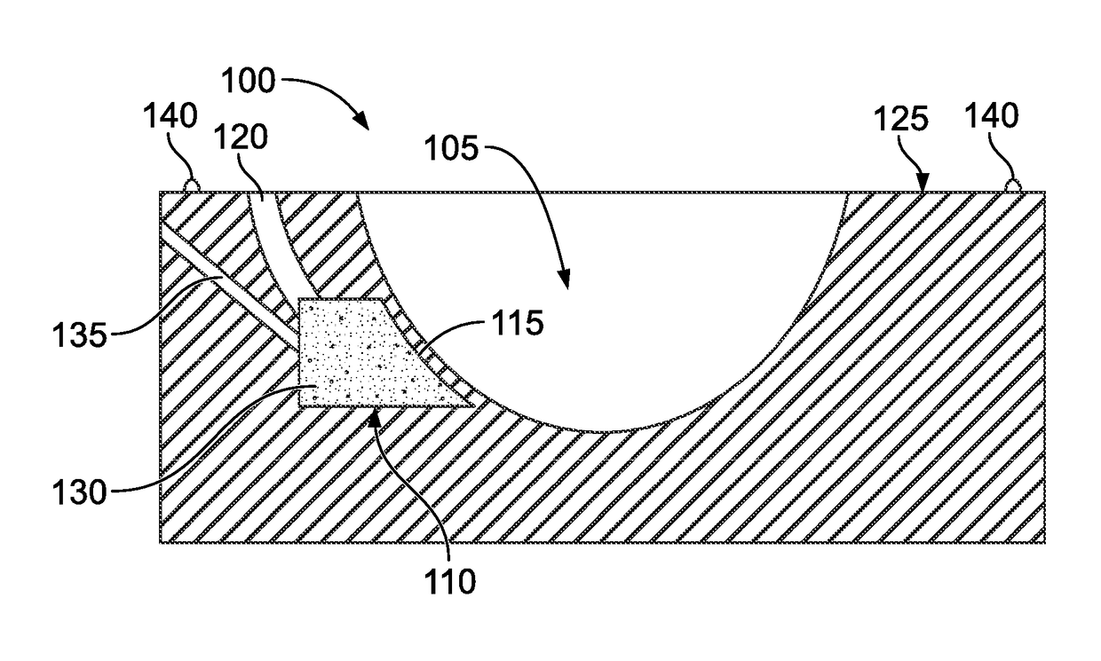
[0034]The examples described in the present disclosure provide the benefits of a traditional chill while eliminating the need to manufacture a near net shape chill to incorporate into a mold body, such as a 3D sand printed mold body. In the examples described herein, there is no longer any need to produce a near net shape chill via a machining operation and insert the chill into a cavity formed in the mold body. Rather, the molds, mold bodies, and methods described herein use a preformed pocket or chill cavity filled with a chill material such as metallic beads, ceramic beads, or specialty sands, that gives ideal thermal properties in the place of a typical chill. This allows the mold body design to 3D print the chill cavity and create a chill wall or barrier of sand between the casting surface and chill cavity. In addition, this minimizes the need for an inventory of chill blocks and could allow for a reduction in cost and personnel.

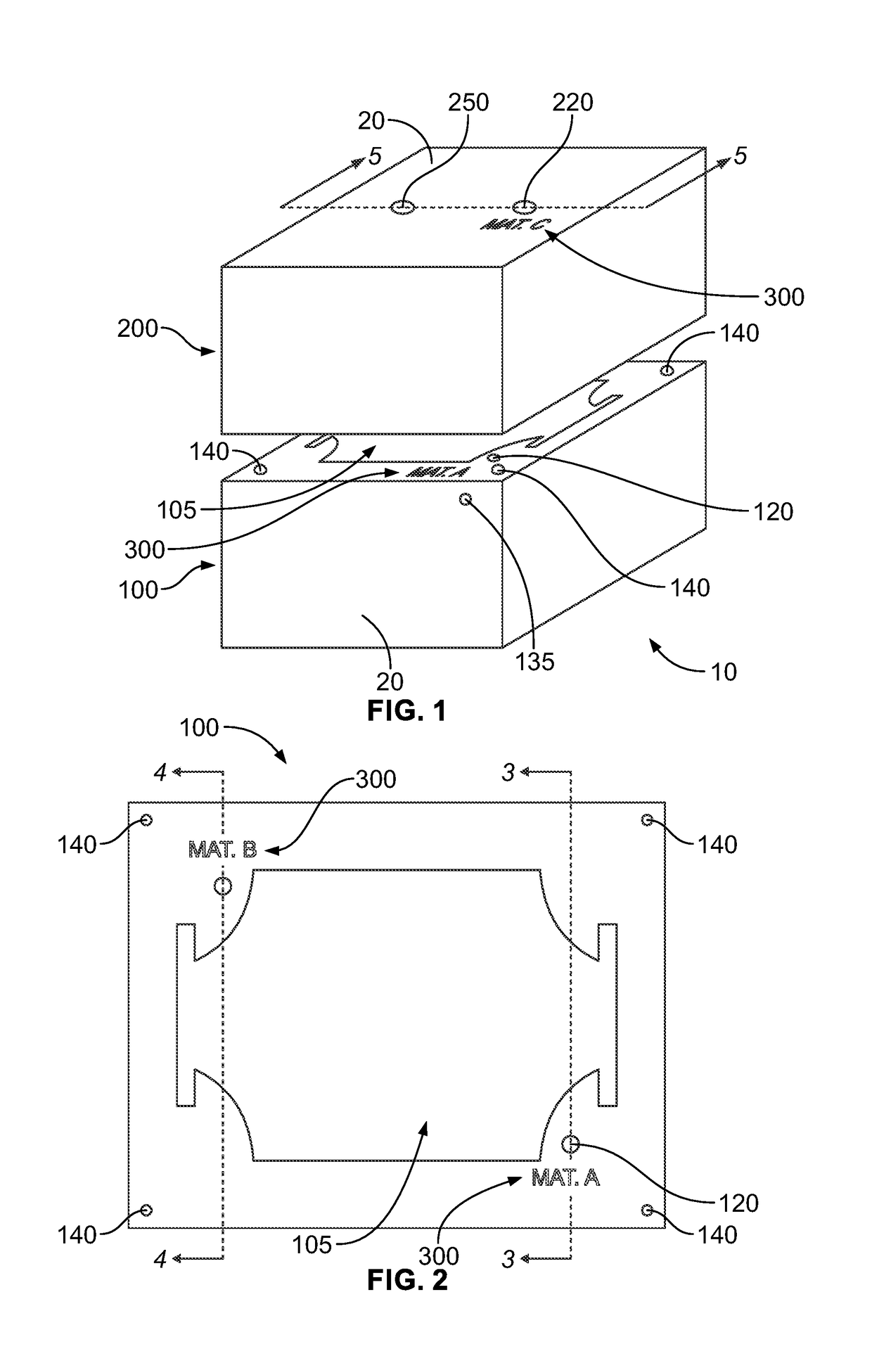
[0035]Referring to FIG. 1, an example mold 10 has...


PUM

PropertyMeasurementUnit
Thermal conductivityaaaaaaaaaa

Abstract

A mold body for use in a mold includes a mold cavity, a chill cavity, a fill channel, and a chill material having a thermal conductivity that is greater than the thermal conductivity of the mold body disposed within the chill cavity. The chill cavity is formed adjacent the mold cavity and is separated from the mold cavity by a chill wall. The fill channel is in communication with the chill cavity and with an exterior surface of the mold body.

Description

FIELD OF THE DISCLOSURE[0001]The present disclosure is directed generally to molds and, more particularly, to mold bodies with integrated chills.BACKGROUND[0002]Foundries use molds, such as sand molds, investment molds, etc., to produce metal and other material castings having a great variety of sizes, shapes, and complexities. Some castings, such as those for valve bodies, have very unique shapes that require a high level of quality to be maintained. To better control the casting process and maintain a high level of quality, chills can be utilized in the molds to more rapidly cool molten metal, which is commonly done to minimize or eliminate shrink defects in all types of metal castings. A typical chill is a piece of metal, or other acceptable material, that is incorporated into a mold body at the edge of the molding cavity and forms a part of the molding cavity in the area where accelerated cooling of the casting is desired. The chill is incorporated into the mold body when the mo...

Claims


Application Information

Patent Timeline
IPC IPC(8): B22D15/04B33Y80/00B22C9/02
CPCB22D15/04B22C9/02B33Y80/00B33Y70/00B22D15/00B33Y10/00Y02P10/25B22C9/00B28B1/001B28B7/34B28B7/342B28B7/346
Inventor BOYLE, ADAM TAYLORVANBECELAERE, NATHAN PADRIAC
Owner FISHER CONTROLS INT LLC
Why Eureka
Eureka Blog
Learn More