Ratchet wrench
- Summary
- Abstract
- Description
- Claims
- Application Information
AI Technical Summary
Benefits of technology
Problems solved by technology
Method used
Image

Examples
Embodiment Construction
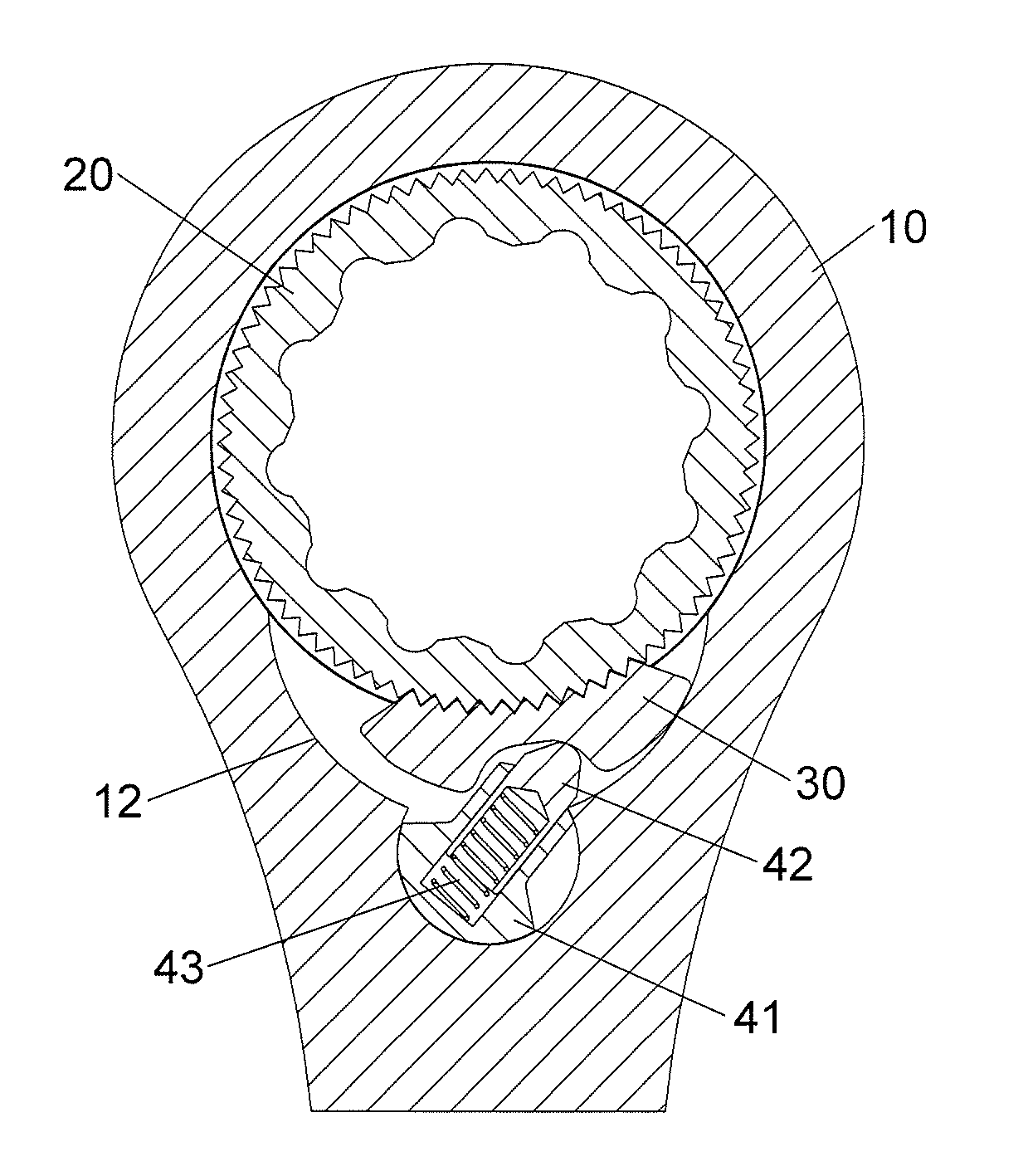
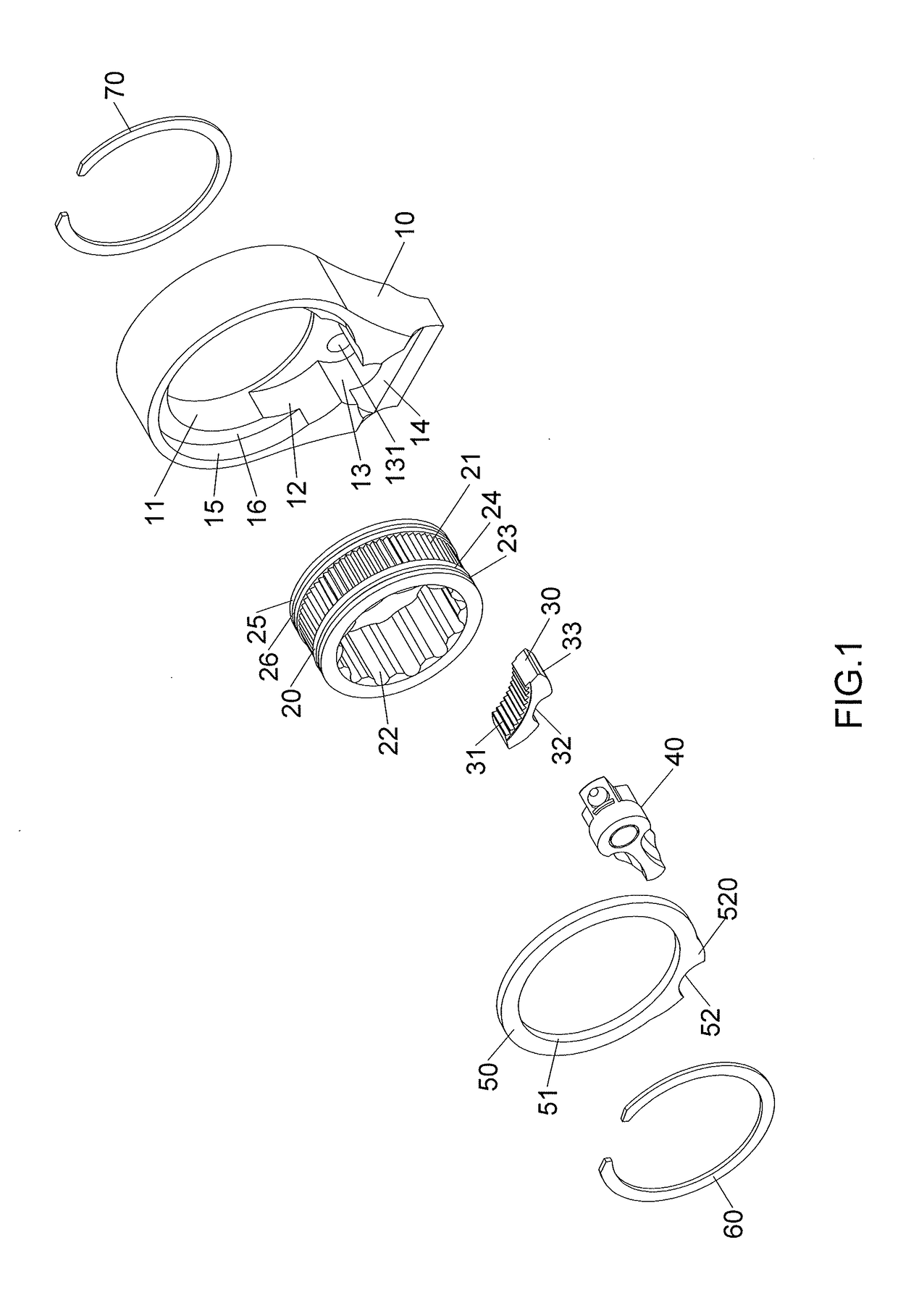
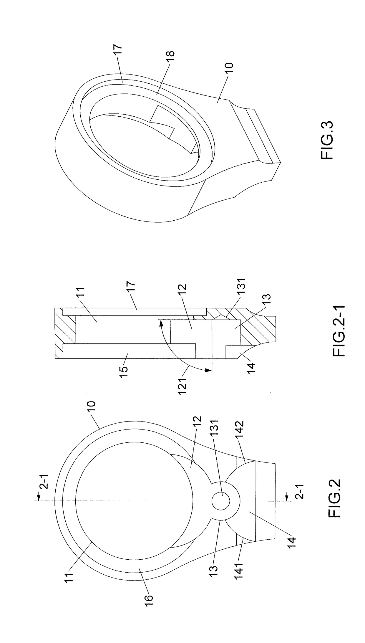
[0026]Referring to FIGS. 1 to 3, and 9 to 11, the ratchet wrench of the present invention comprises a body 10 having a through hole 11 defined through the top and the bottom thereof. The through hole 11 has a first recess 12 defined in the inner periphery thereof, and the center of the first recess 12 is located in the through hole 11. The diameter of the first recess 12 is smaller than the diameter of the through hole 11. A first angle 121 is defined between the bottom of the first recess 12 and the inner periphery of the first recess 12. The first angle 121 is between 90 to 120 degrees. Preferably, the first angle 121 is between 90 to 100 degrees. A second recess 13 is defined in the inner periphery of the first recess 12. The top ends of the first and second recesses 12, 13 are opened to the top of the body 10. The diameter of the second recess 13 is smaller than the diameter of the first recess 12. The second recess 13 has a cone-shaped first positioning portion 131 defined on t...
PUM
 Abstract
Description
Claims
Application Information
 - R&D
- Intellectual Property
- Life Sciences
- Materials
- Tech Scout
- Unparalleled Data Quality
- Higher Quality Content
- 60% Fewer Hallucinations
Browse by: Latest US Patents, China's latest patents, Technical Efficacy Thesaurus, Application Domain, Technology Topic, Popular Technical Reports.
© 2025 PatSnap. All rights reserved.Legal|Privacy policy|Modern Slavery Act Transparency Statement|Sitemap|About US| Contact US: help@patsnap.com