
Base for conveyor belt scraper

a technology for scrapers and conveyor belts, applied in the direction of conveyor parts, cleaning, transportation and packaging, etc., can solve the problems of high labor costs, scraper installation and recovery, and high cost of liquid nitrogen us

Active Publication Date: 2018-08-09
BRELKO PATENTS
View PDF1 Cites 1 Cited by
  • Summary
  • Abstract
  • Description
  • Claims
  • Application Information

AI Technical Summary

Benefits of technology

This patent describes a conveyor belt scraper with a base and a scraper element. The base has an elongate body with a bridging piece and retention sections on its sides. The retention sections may have keying formations which bond to the material used to mold the base. The scraper element has a scraper member which is molded onto the base or attached to it using fasteners. The technical effects of this invention are a more durable and flexible conveyor belt scraper that can withstand high temperatures and the use of corrosive materials, and a more efficient and cost-effective manufacturing process.

Problems solved by technology

Some properties which make polyurethane suitable for use as a scraper can however, present problems during installation and recovery of the scraper, when worn.
The use of liquid nitrogen is expensive, and assembly of the base requires a fair amount of labour.

Method used


Image

  • Base for conveyor belt scraper
  • Base for conveyor belt scraper
  • Base for conveyor belt scraper

Examples


Embodiment Construction

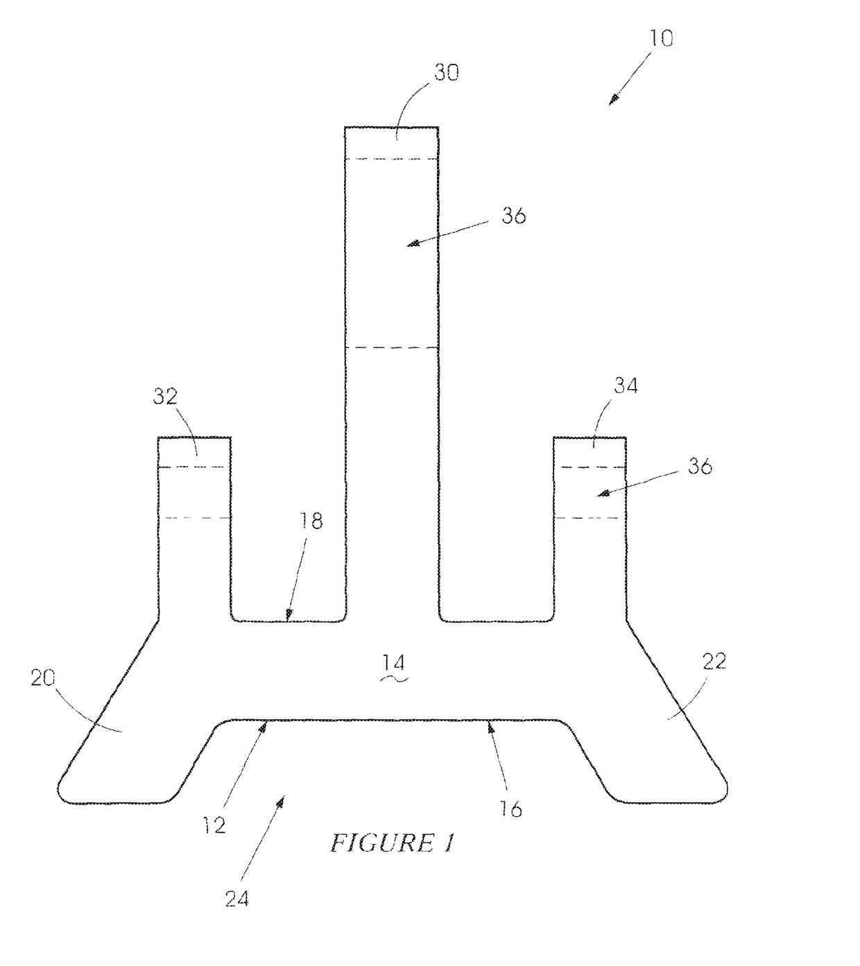
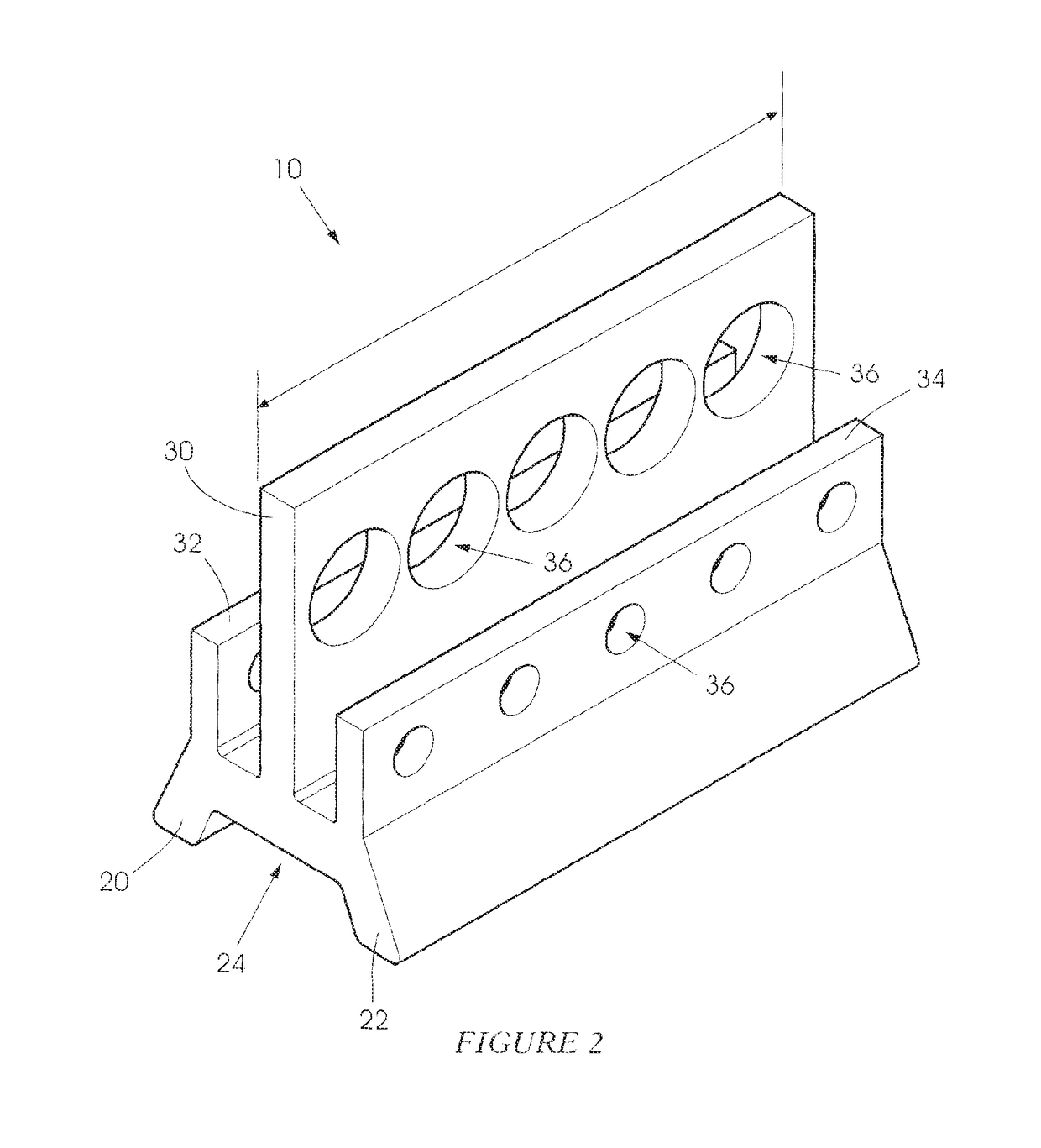
[0020]FIG. 1 and FIG. 2 are a view in cross-section and a perspective view, respectively, of a base 10 for a conveyor belt scraper according to the invention.

[0021]The base 10 includes a body 12 with a bridging piece 14 which has a first side 16 and a second, opposed side 18. First and second, spaced apart, diverging legs 20 and 22 respectively, which define a gap 24 between them, project from the first side 16.

[0022]Three retention sections 30, 32 and 34 respectively extend from the second side 18, away from the legs 20 and 22. Each retention section, in outline as shown in FIG. 2, is generally rectangular. The section 30 is centrally positioned on the second side 18 and is the largest of the three sections. The sections 32 and 34 are spaced from the section 30 and are, in effect, at respective opposed extremities of the bridging piece 14.

[0023]Each retention section is formed with a respective number of keying formations in the form of holes 36 which extend transversely through th...


PUM


Abstract

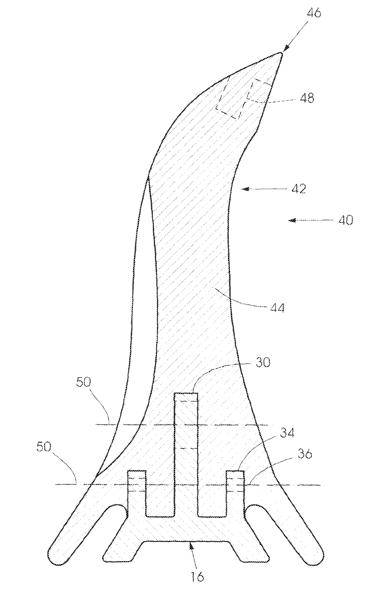
A conveyor belt scraper (40) which includes a base (10) and a scraper element (42) which is moulded to the base (10).

Description

BACKGROUND OF THE INVENTION[0001]This invention relates generally to a conveyor belt scraper and more particularly to a base for use with a conveyor belt scraper.[0002]One type of conveyor belt scraper is made from a tough, resiliently deformable, material such as polyurethane. Typically, this type of belt scraper, which is integrally moulded, has a retention formation which is engageable with a sliding action with a suitable channel in a holder. Some properties which make polyurethane suitable for use as a scraper can however, present problems during installation and recovery of the scraper, when worn. This is because the polyurethane is “sticky” and tends to cling to a holder, resisting relative sliding movement.[0003]Another type of scraper has a base which is square in cross-section and which is positioned inside a tubular holder which is also of square cross-section. There is an offset between the base and the holder so that, inside the holder, four triangular voids are formed ...

Claims


Application Information

Patent Timeline
Patent Type & Authority Applications(United States)
IPC IPC(8): B65G45/12
CPCB65G45/12
Inventor CHRISTIAN, PAUL
Owner BRELKO PATENTS
Learn More