
Temperature sensor assembly

a temperature sensor and assembly technology, applied in the field of air temperature sensors, can solve the problems of not preventing the removal and assembly, and achieve the effects of preventing inadvertent displacement, and reducing the risk of damag

Inactive Publication Date: 2009-07-23
GM GLOBAL TECH OPERATIONS LLC
View PDF3 Cites 7 Cited by
  • Summary
  • Abstract
  • Description
  • Claims
  • Application Information

AI Technical Summary

Benefits of technology

The patent describes a sensor assembly for installation in a hole in a duct. The assembly includes a sensor and a body with elastic ribs that deflect into the duct wall to secure the sensor in place. The assembly is easy to install and is retained in the duct with a tight fit, preventing displacement. The elastic ribs make it easy to insert the assembly into the duct and can be removed without causing damage. The technical effects of this design are its compact size, reliability, and versatility in duct thickness and hole size.

Problems solved by technology

After installation, the ribs resist, but do not prevent removal, of the assembly from the duct.

Method used


Image

  • Temperature sensor assembly
  • Temperature sensor assembly
  • Temperature sensor assembly

Examples


Embodiment Construction

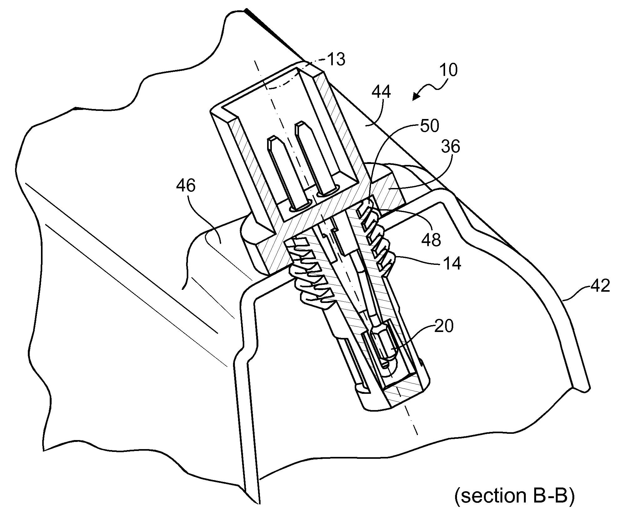
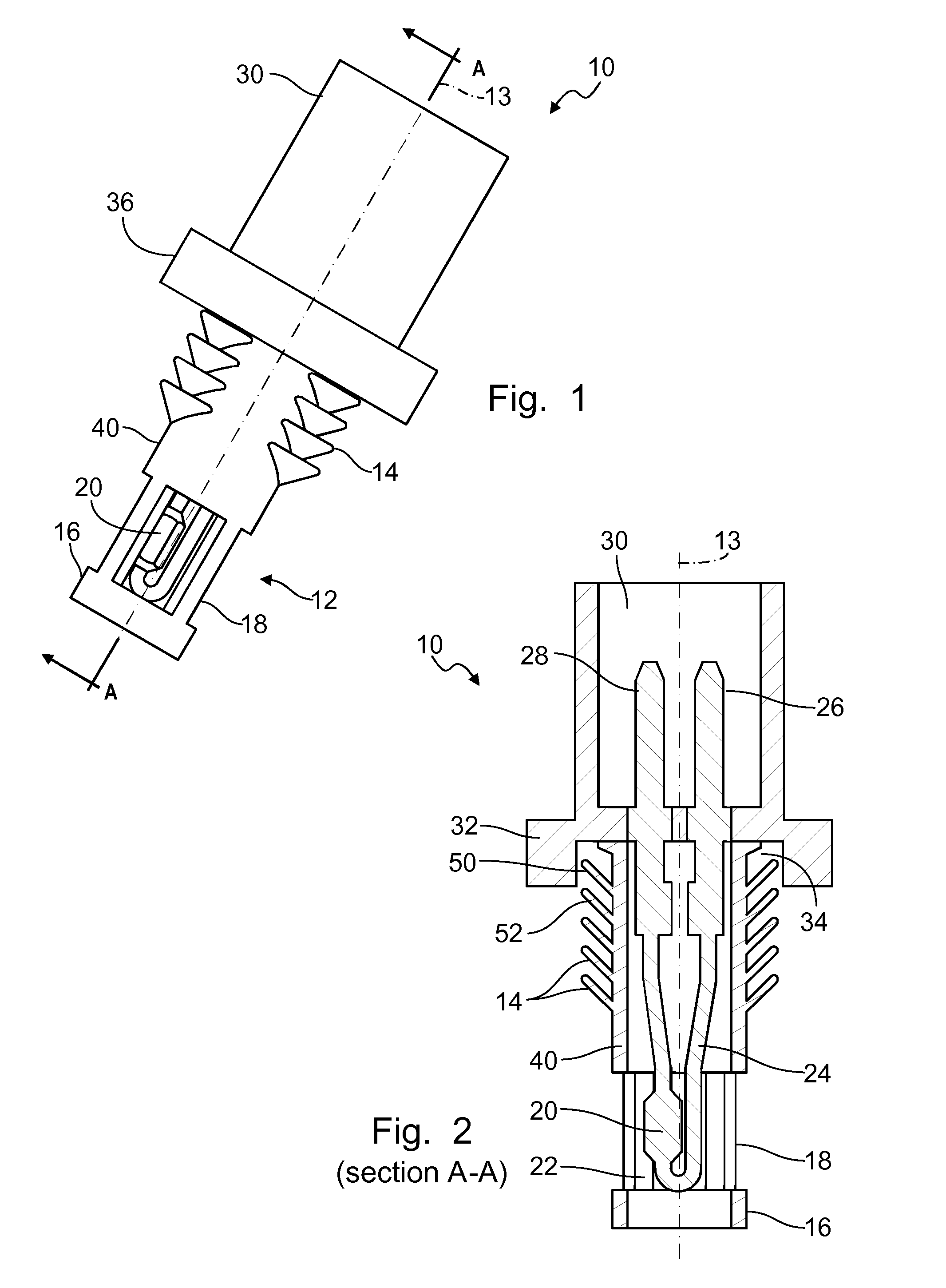
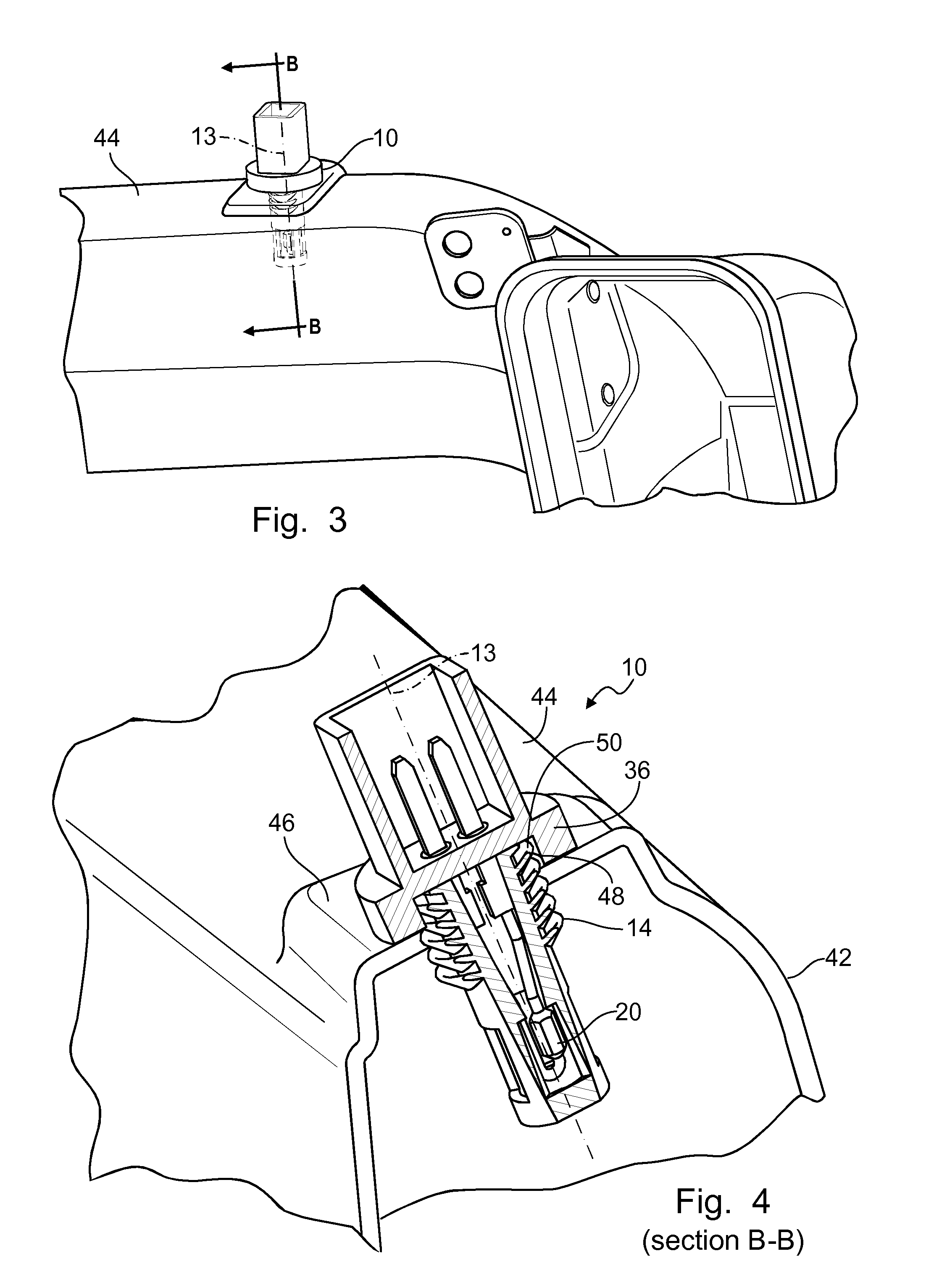
[0013]FIGS. 1 and 2 illustrate an electronic duct air temperature sensor assembly 10 that includes a body 12 having a central axis 13 and formed with a series of ribs 14 spaced along the body, a cylindrical base 16 and a cage 18 containing an air temperature sensor 20. The cage 18 includes open passages 22 that allow air in the duct to flow through the assembly 10 and across the sensor 20.

[0014]Electric conducting leads 24 extend from sensor 20 along the body 12 to terminals 26, 28, which are enclosed in a receptacle portion 30 of the body 12, into which receptacle is inserted a plug secured to a wiring harness (not shown) for electrically engaging the terminals. The body 12 includes a cylindrical shoulder 32, which is formed with an annular recess 34.

[0015]FIG. 2 shows that the ribs 14 extend radially outward and upward toward the shoulder 32. The ribs 14 are relatively thin, flexible, elastically displaceable and resilient, i.e., they tend to return to the position shown in FIG. 2...


PUM

PropertyMeasurementUnit
thicknessaaaaaaaaaa
thicknessaaaaaaaaaa
elastically resilientaaaaaaaaaa

Abstract

A sensor assembly for installation in a hole formed in a wall of a duct, includes a sensor, and a body containing the sensor and extending along an axis, the body including a shoulder, and a series of elastically resilient ribs spaced mutually along the axis and inclined outward and toward the shoulder, the ribs undergoing flexural displacement into engagement with the wall as the assembly is inserted into the hole.

Description

BACKGROUND OF INVENTION[0001]The present invention relates generally to heating ventilation and air conditioning (HVAC) systems, and, more particularly to an air temperature sensor for an automatically controlled HVAC system.[0002]Automatic control of HVAC systems requires that the correct temperature of air flowing through the air ducts and outlets be determined. An electronic sensor, installed in an air duct, produces a signal representing the temperature of air flowing in an air duct. The sensor includes a NTC thermistor and two leads coated with epoxy, housed in a plastic body.[0003]It is conventional to form HVAC air ducts by a blow molding process that causes the thickness of the duct walls to vary from 0.70 mm. to 2.25 mm. A conventional sensor assembly includes a plastic retainer having two ribs spaced about 1.5 mm. apart, which ribs engage the duct wall when the sensor assembly is inserted into the duct. A temperature probe portion of the assembly is inserted in the retaine...

Claims


Application Information

Patent Timeline
Patent Type & Authority Applications(United States)
IPC IPC(8): G01K1/00G01K7/00
CPCG01K1/14
Inventor KHAN, EKRAMUL H.VALENCIA, JR., PABLO
Owner GM GLOBAL TECH OPERATIONS LLC
Learn More