Head clamping apparatus for magnetic disk tester and magnetic disk tester

a technology of magnetic disk tester and clamping apparatus, which is applied in the direction of maintaining the head carrier alignment, functional testing of recording heads, instruments, etc., can solve the problems of insufficient precision control of magnetic heads, difficult for related art to accurately control the position of magnetic heads, and related art interference, so as to prevent the breakage effect of microactuators

Inactive Publication Date: 2005-08-16
UNIPULSE
View PDF8 Cites 22 Cited by
  • Summary
  • Abstract
  • Description
  • Claims
  • Application Information

AI Technical Summary

Benefits of technology

[0025]As the density of tracks on a magnetic disk increases, the related art that corrects only an off-track error caused by a thermal drift will be insufficient to precisely control the magnetic heads. It is required to correctly control the positions of the magnetic heads on a magnetic disk on a sector-by-sector basis by eliminating the influence of disturbances such as airflows and vibrations.
[0028]A first object of the present invention is to provide a head clamping apparatus for a magnetic disk tester, capable of driving a piezo-electric actuator at high frequencies to easily and speedily make a magnetic head trace a target track.
[0029]In order to accomplish the object, a first aspect of the present invention provides a head clamping apparatus for a magnetic disk tester. The head clamping apparatus positions a magnetic head on a target track among concentric tracks formed on a magnetic disk that is revolving. The head clamping apparatus has a microactuator stage that supports the magnetic head and is driven by a microactuator in a track crossing direction. When energized, the microactuator minutely moves the microactuator stage in a horizontal direction in proportion to an input voltage to the microactuator. This results in minutely horizontally adjusting the magnetic head attached to the microactuator stage. The microactuator stage is small and a driving part thereof is light, to improve the rigidity of the microactuator stage as a whole. Consequently, the microactuator can drive the microactuator stage at high frequencies.
[0031]A third aspect of the present invention provides the stage part of any one of the first and second aspects with a cut to divert an external force applied to the stage part into a compressing direction of the microactuator. The microactuator is structurally strong against a compressing force and is vulnerable to a tensile force, and therefore, may be broken if a tensile force is applied thereto due to an external force to the stage part. The cut on the stage part diverts such an external force on the stage part into the compressing direction of the microactuator, to effectively prevent the breakage of the microactuator.
[0032]A second object of the present invention is to provide a magnetic disk tester capable of directly sensing the position of a magnetic head as near to a core of the magnetic head as possible. The tester uses the position thus obtained for feedback control to precisely control the position of the magnetic head.
[0033]In order to accomplish the second object, a fourth aspect of the present invention provides a magnetic disk tester having a head clamp installed on a head load mechanism that is arranged on a coarse stage. A piezo-stage for holding a magnetic head assembly is attached to the head clamp. A reflective scale is attached to a back face of the piezo-stage. The reflective scale is formed by depositing light-shield stripes on a film at predetermined intervals. A laser head is attached to the coarse stage. The laser head has a light emission / reception part facing the light-shield stripes of the reflective scale. A positioning unit controls the position of the head clamp. The laser head emits a laser beam, which is reflected by the reflective scale. According to the reflected beam, the positioning unit detects the position of the magnetic head assembly on a magnetic disk. According to the detected position and a reference position, an error signal is generated, and based on the error signal, the position of the head clamp is precisely controlled.

Problems solved by technology

As the density of tracks on a magnetic disk increases, the related art that corrects only an off-track error caused by a thermal drift will be insufficient to precisely control the magnetic heads.
It is difficult for the related art to accurately control the position of the magnetic head 234.
In addition, the piezo-actuator 237 itself is relatively heavy and this deteriorates the responsiveness thereof.

Method used


Image

  • Head clamping apparatus for magnetic disk tester and magnetic disk tester
  • Head clamping apparatus for magnetic disk tester and magnetic disk tester
  • Head clamping apparatus for magnetic disk tester and magnetic disk tester

Examples


first embodiment

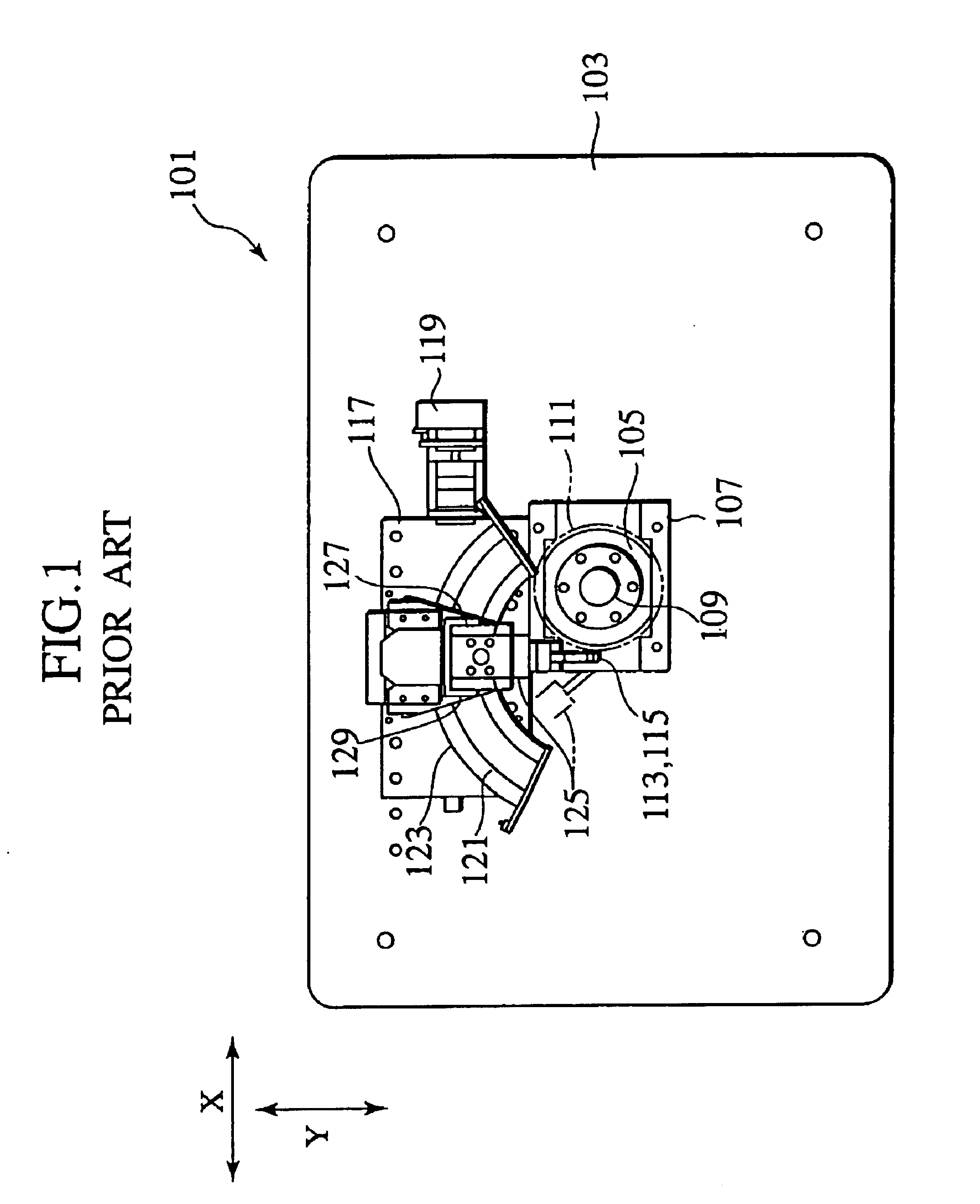
[0054]A head clamping apparatus for a magnetic disk tester according to the first embodiment of the present invention will be explained. The head clamping apparatus of the first embodiment is widely applicable not only to the magnetic disk tester of the related art of FIG. 1 but also to other disk testers.

[0055]FIG. 7 shows the head clamping apparatus 27 of the first embodiment installed on a head loader (not shown) of a magnetic disk tester. The apparatus 27 has a pair of down-face and up-face magnetic heads 15 and 17. Unlike the related arts, a base of the head loader is not provided with a microactuator having a piezo-element. The present invention is characterized by installing the microactuator on another structural part.

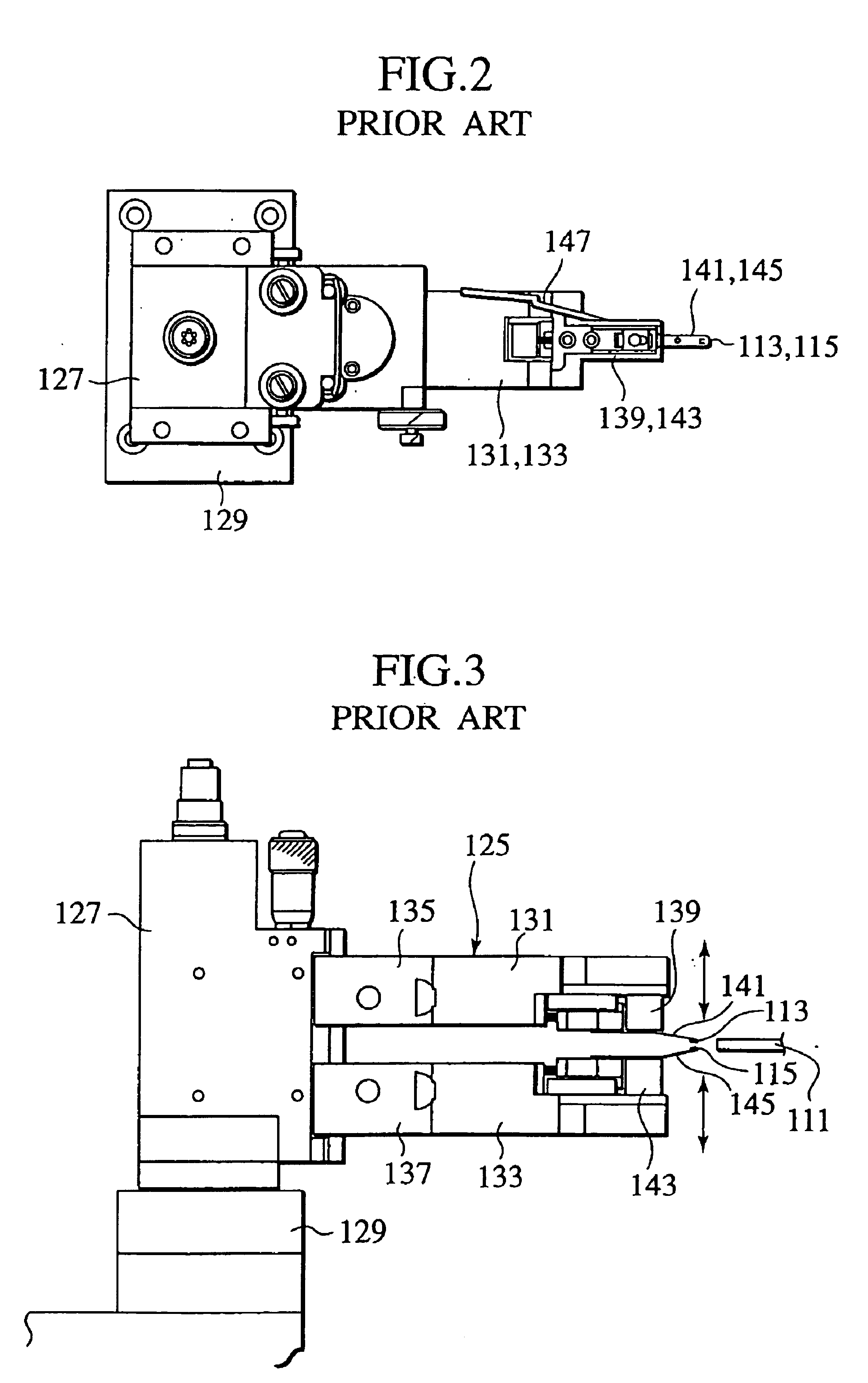
[0056]The head clamping apparatus 27 has an upper head clamp 35 and a lower head clamp 37. The upper head clamp 35 is attached to an upper fitting base 39 that is vertically movable along a Z-axis. The lower head clamp 37 is attached to a lower fitting base 41 ...

second embodiment

[0076]FIG. 11 schematically shows the magnetic disk tester according to the second embodiment. FIG. 12 is a perspective view showing the tester. The tester includes the tester proper, an electric circuit, a computer, and a measuring unit.

[0077]The tester 210 has a two-dimensional coarse stage 214 consisting of an X-axis stage 214a that is movable along a X-axis and a Y-axis stage 214b that is movable along a Y-axis. Two coarse stages 214 are symmetrically arranged about a magnetic disk 212 that is driven by a spindle 209.

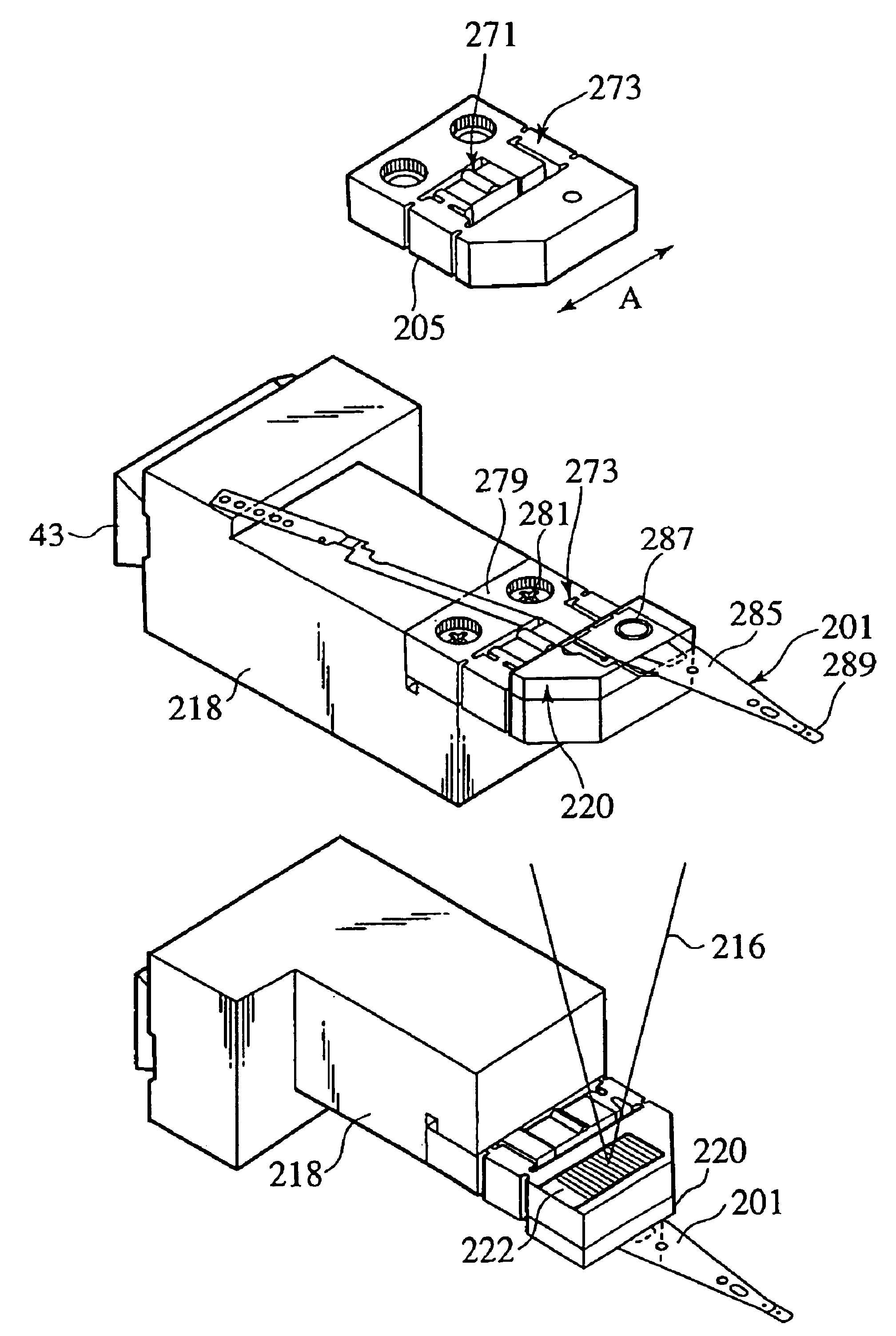
[0078]On the coarse stage 214, a head mechanism (head load mechanism) 215 is connected. The head mechanism 215 has a laser head 217 and a head clamp 218. The tester 210 also has a coarse stage glass scale to detect the position of the coarse stage 214 and coarse stage motors 219 to drive the coarse stage 214.

[0079]The head clamp 218 supports a magnetic head assembly (HGA (head gimbal assembly)) 201 to write and read information to and from the magnetic disk 212. In ...

third embodiment

[0106]The burst patterns of FIG. 16A provide a position error signal with a linear control range of ±Tw / 2 at most even under ideal conditions. The magnetic head assembly 201 usually involves a read / write offset. This type of offset is caused by a skew angle of a magnetic head and corresponds to the difference between the centers of write and read cores of the magnetic head. Taking the offset into account, the linear control range of ±Tw / 2 is insufficient for high stability.

[0107]FIG. 17 shows examples of servo burst patterns A to E that expand the linear control range to ±(¾)Tw to detect an off-track of ±3 tracks. The burst pattern B is on-track with ΔX=0, and therefore, corresponds to data patterns. Each of the other burst patterns A, C, D, and E involves two patterns at the same timing on different tracks. FIG. 18 shows the track positions of the burst patterns.

[0108]Assuming that Vth is a threshold to determine the presence of a burst pattern, Vt is a control voltage correspondin...


PUM

PropertyMeasurementUnit
electric resistivityaaaaaaaaaa
roughnessaaaaaaaaaa
weightaaaaaaaaaa

Abstract

A magnetic disk tester has a head clamp (35, 218) to position a magnetic head (15, 289). The head clamp has a micromotion stage (55, 273) provided with a stage (59, 205) which is horizontally moved by a piezo-element (77). The magnetic head is attached to the piezo-stage (55, 273). On the head clamp (218), a reflective scale (222) is attached to a back face of the piezo-stage, and a laser head (217) is oriented toward the head clamp (218). According to a reflected laser beam from the reflective scale, the position of the magnetic head (289) is detected. An error signal indicating the difference between the detected position and a reference position is used to control the head clamp (218). The piezo-element can operate at high frequencies, to easily make the magnetic head trace a target track and improve the positioning accuracy of the magnetic head.

Description

BACKGROUND OF THE INVENTION[0001]1. Field of the Invention[0002]The present invention relates to a head clamping apparatus for a magnetic disk tester that tests the electromagnetic transducing characteristics of a magnetic disk and magnetic head that are essential parts of a hard disk drive. In particular, the present invention relates to a head clamping apparatus for positioning a magnetic head onto a target track on a magnetic disk and measuring the write / read characteristics of the magnetic head, and to a magnetic disk tester provided with a head clamping function.[0003]2. Description of the Related Art[0004]The performance of hard disk drives is improving, and to cope with it, the performance of testers for testing the electromagnetic transducing characteristics of magnetic disks and magnetic heads used for the hard disk drives must be improved.[0005]To deal with increasing track densities in the hard disk drives, magnetic heads must have narrow cores. To correctly measure the c...

Claims


Application Information

Patent Timeline
Patent Type & Authority Patents(United States)
IPC IPC(8): G11B5/596
CPCG11B5/59611G11B5/59627G11B5/483G11B5/455
Inventor TAKAGI, HITOSHIFUKUOKA, KIYOTAKAHATANO, MAMORUFUJII, KATSUHIRO
Owner UNIPULSE
Why Eureka
Try Eureka