
Pull-push rod

a technology of pulling rods and threads, applied in the direction of pulling rod connections, controlling members, ropes and cables for vehicles/pulleys, etc., can solve the problems of time-consuming and difficult execution of installation steps, and achieve the effect of good noise control and increased play in threads with tim

Active Publication Date: 2013-02-12
GMT GUMMI METALL TECHN +1
View PDF33 Cites 9 Cited by
  • Summary
  • Abstract
  • Description
  • Claims
  • Application Information

AI Technical Summary

Benefits of technology

The invention relates to a pull-push rod with an anti-rotation device that can be easily and quickly installed in confined spaces. This solution eliminates the need for a separate locking mechanism and ensures that the pull-push rod automatically relocks after each rotation of the body. Additionally, a spring element can be included to prevent noise from occurring due to play in the threads.

Problems solved by technology

The execution of these installation steps can, in particular in confined spaces, be difficult and time-consuming.

Method used


Image

  • Pull-push rod
  • Pull-push rod
  • Pull-push rod

Examples


Embodiment Construction

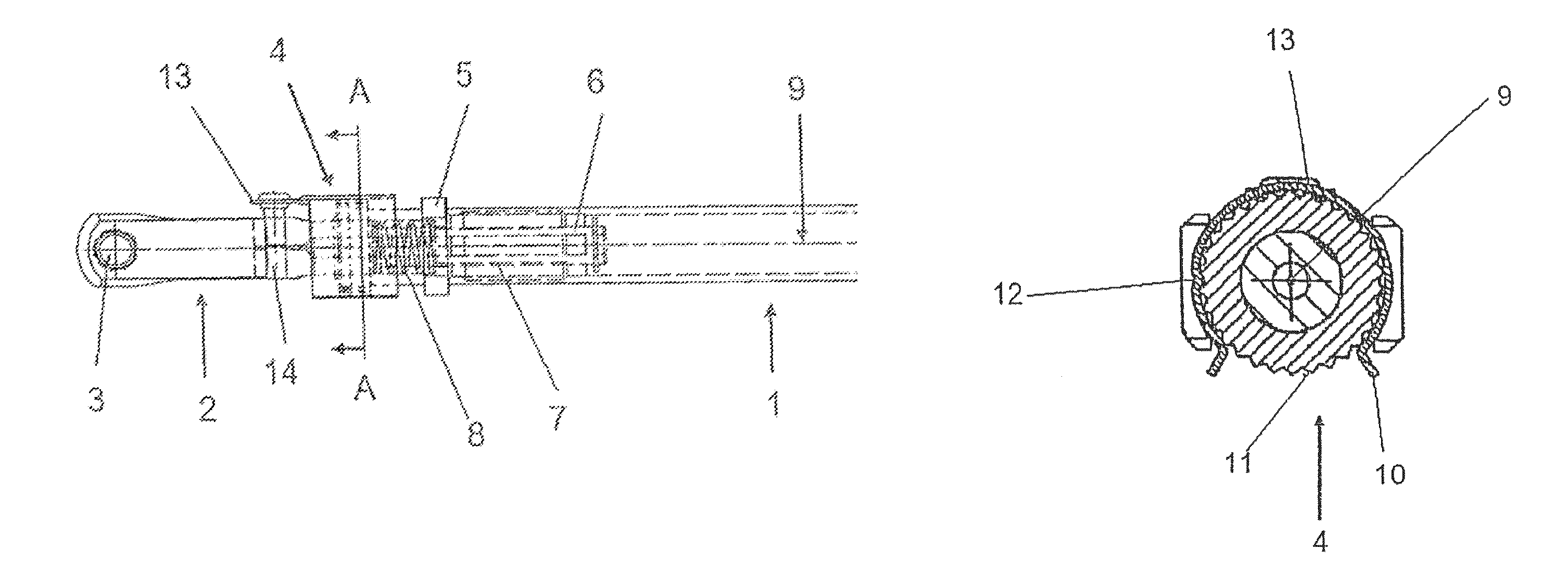
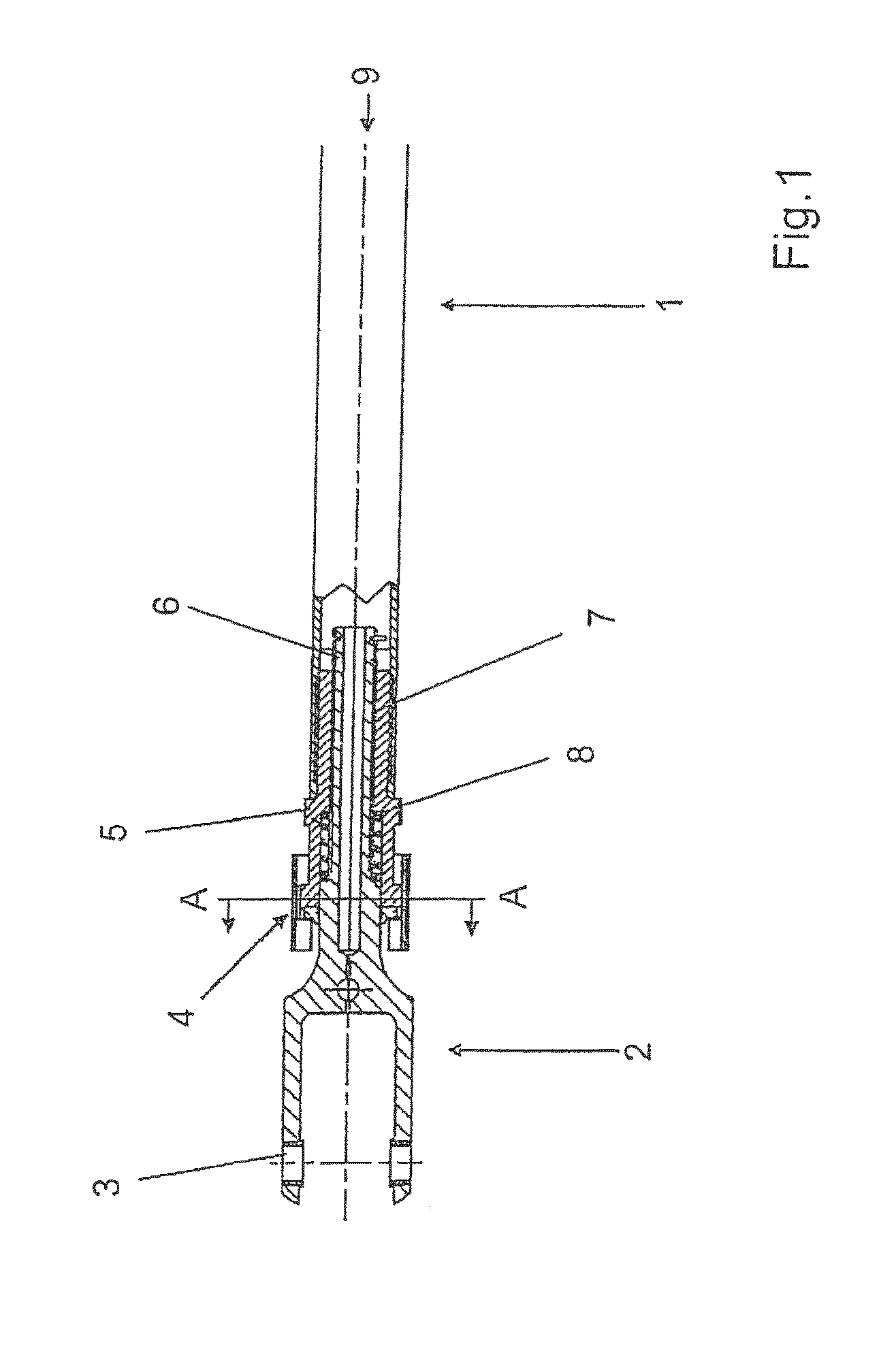
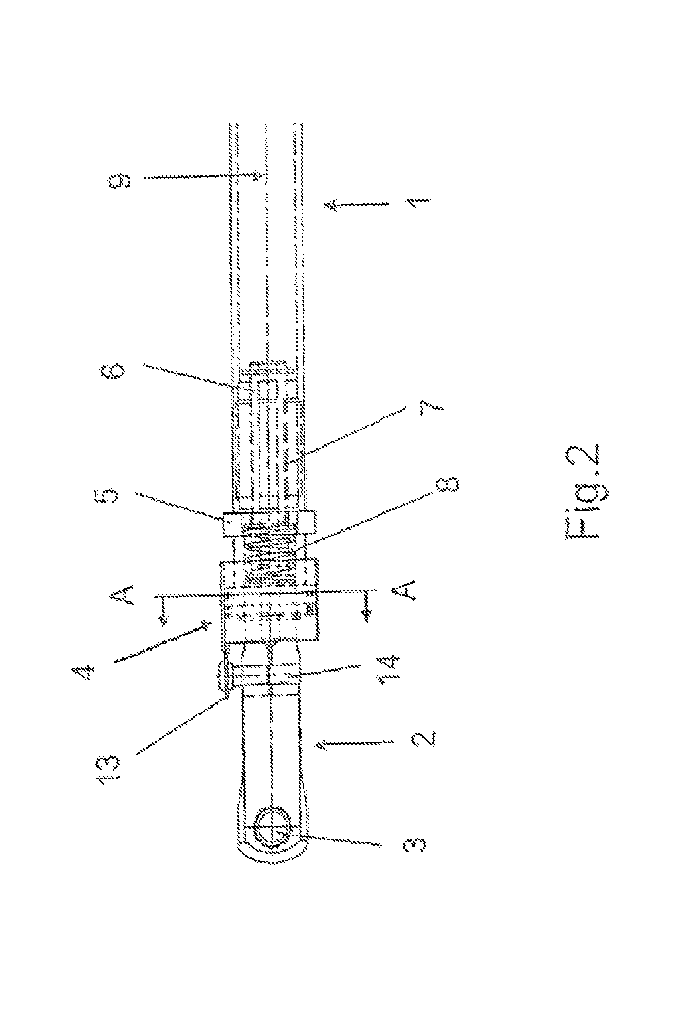
[0022]FIGS. 1 and 2 show one end of a tubular body 1, on which an adapter 2 is arranged, wherein in FIG. 2 the pull-push rod is represented rotated through 90° relative to FIG. 1. The body 1 and the adapter 2 are connected together via a thread arrangement 7. The thread arrangement 7 has a first thread on the inner wall of an insert element 5 connected with the body 1, and a second thread on the outer circumference of the shaft 6 of the adapter 2. The insert element 5 surrounds the shaft 6 and at the same time accommodates a spring element (torsion spring) 8. The spring element 8 presses the adapter 2 and the insert element 5 in opposing directions, as a result of which the threads of the thread arrangement 7 are pressed against each other. This has the advantage that noise generation in the pull-push rod is thus avoided. When the pull-push rod is under load, forces act along the axis of rotation 9, as a result of which the play in the thread arrangement 7 increases in the course of...


PUM


Abstract

A threaded device is embodied in the form of an anti-twisting stop which is rotatably connected to a traction-pressure rod. Two oppositely located ratchet devices are connected by a body to stop the traction-pressure rod in several rotational positions with a predetermined locking force and, afterwards, to release it each time. The threaded device facilitates the mounting of the traction-pressure rod by the fact that the twisting should not be locked by additional handling, thereby making it possible to carry out a fine adjustment without additional measures. The ratchet device comprises, for example, two ratchet elements provided with one or several catch lugs or a metal or plastic ring part on one side and a gear rim on the other side. In addition, the threaded device can be provided with a spring element and a second anti-noise threaded device.

Description

CROSS REFERENCES TO RELATED APPLICATION[0001]This application claims priority from German Application Priority Number 20 2004 016 321.7, priority date Oct. 20, 2004, and PCT Application number PCT / EP05 / 11229, filed Oct. 19, 2005, each of which is hereby incorporated herein by reference in the respective entirety of each.FIELD OF THE INVENTION[0002]The invention concerns a pull-push rod, in particular for guidance and mechanical support in machinery, aircraft and vehicle construction.DESCRIPTION OF THE RELATED ART[0003]Pull-push rods of this kind comprise in general an at least essentially tubular body at each end of which an adapter is located for the installation of the pull-push rod.[0004]Pull-push rods of this kind are in general adjustable in their length in order that they can compensate for tolerances or adapt to a prescribed distance separating the installation points. In order to prevent inadvertent rotation of the pull-push rod in its installed state, an appropriate anti-ro...

Claims


Application Information

Patent Timeline
IPC IPC(8): F16B7/06F16B7/18
CPCF16B7/182F16C7/06Y10T403/7033Y10T74/2158Y10T403/295F16B7/14
Inventor UHL, ALBERTGOMEZ, FRANCISCOKOCH, SOEREN
Owner GMT GUMMI METALL TECHN
Learn More