Device for lowering flow noises

a flow noise and noise reduction technology, applied in the direction of fuel intake silencers, fuel intakes, pipe elements, etc., can solve the problems of increased air mass throughput, undesirable frequency changes and/or damping characteristics, unmanageable imbalances, etc., to achieve reliable sealing effect, elastic properties, and reliable sealing effect

Active Publication Date: 2018-08-09
UMFOTEC +1
View PDF16 Cites 4 Cited by
  • Summary
  • Abstract
  • Description
  • Claims
  • Application Information

AI Technical Summary

Benefits of technology

[0011]By designing the sealing ring as a ring cap that reaches over the collar, said cap having on the one hand an outer lateral surface that lies in a sealing manner against the wall surface of the adjacent sleeve (the outer sleeve or inner sleeve, depending on the arrangement of the collar), and on the other hand said cap having an inner lateral surface facing away from the outer lateral surface, and lying in a sealing manner against the end face of the free end of the collar, it is possible to bridge a relatively large intermediate space between the free end of the radial collar and the adjacent sleeve with a reliable sealing effect. Alternatively, the ring cap, on the one hand, can lie in a sealing manner with its outer lateral surface against the wall surface of the adjacent sleeve and, on the other hand, it can lie in a sealing manner, with an annular radial contact surface extending parallel to the radial collar, against the radially arranged side surface of the collar facing toward the ring cap. With the alternative solution, an even larger intermediate space between the free end of the radial collar and the adjacent sleeve can be bridged with a reliable sealing effect.
[0012]The sealing ring may have elastic properties. The sealing ring therefore constitutes an elastic equalizing element that balances out the differing expansions of different materials that have different coefficients of thermal expansion, and it also reliably seals the volume chambers.
[0013]In one embodiment, the sealing ring with its outer lateral surface lies under tension in a sealing manner against the wall surface of the sleeve adjacent to the free end of the collar, and the sealing ring with its inner lateral surface facing away from the outer lateral surface lies, also under tension in a sealing manner, against the peripherally extending end face of the free end of the collar. The sealing ring can thus abut, with its annular radial contact surface extending parallel to the radial collar, against the radially arranged lateral surface of the collar facing toward the ring cap. Thanks to their relatively simple geometric shape, both the radial collar as well as the sealing ring can thus be produced and mounted relatively easily and inexpensively.
[0014]The cap-shaped design of the sealing ring allows the collar to be configured as a simple peripheral wall in the radial direction. Moreover, the sealing ring can be relatively easily and reliably placed on the collar and the sleeves can be pushed inside each other without displacing the sealing ring. The cap-shaped design additionally has the advantage of allowing the wall thickness of the peripherally extending collar to be relatively thin. In turn, this means that the length of two adjacent volume chambers can be reduced or, if they remain the same length, the volume of the volume chambers can be enlarged.
[0015]The sealing ring may be constructed from a wire mesh. Constructing the sealing ring from wire mesh results in the desirable elastic properties. In addition, a wire mesh has high temperature resistance and good damping characteristics. However, the sealing ring can also be constructed from a silicate fiber mesh or a compound mesh made of wire and silicate fibers.
[0016]The outer lateral surface of the sealing ring may lie under tension and in a sealing manner, against the wall surface of the sleeve adjacent to the free end of the collar, and the sealing ring, with the annular radial contact surface extending parallel to the radial collar, lies under tension also in a sealing manner against the lateral surface of the collar facing toward the ring cap. As described above, this makes it possible to bridge a relatively large intermediate space between the free end of the radial collar and the adjacent sleeve with a reliable sealing effect.

Problems solved by technology

When exhaust gas turbochargers, for example, are used in conjunction with internal combustion engines, undesirable flow noises result due to high engine speeds, unmanageable imbalances, disruptions due to production-related warping (e.g. vanes) as well as increased air mass throughput.
With regard to the known device, which has essentially proven effective, it is disadvantageous that the collar separating the chambers does not provide adequate separation or sealing, depending on existing tolerances, and as a result undesirable frequency changes and / or changes in the damping characteristics can occur.
With regard to this known device, especially when different materials with different coefficients of expansion are used for the outer sleeve and the inner sleeve, and due to existing tolerances, it is disadvantageous that the radial collar with its free end, fails to adequately separate or seal the chambers it subdivides, even when an O-ring seal is arranged between the collar and the adjacent sleeve, thereby enabling the occurrence of undesired frequency changes and / or changes to the damping characteristics.
With regard to this known device as well, it is disadvantageous that, depending on existing tolerances, the collar separating the chambers from each other fails to sufficiently separate or seal them, thereby enabling the occurrence of undesirable frequency changes and / or changes in the damping characteristics.

Method used


Image

  • Device for lowering flow noises
  • Device for lowering flow noises
  • Device for lowering flow noises

Examples


Embodiment Construction

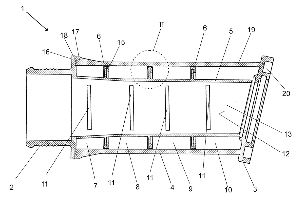
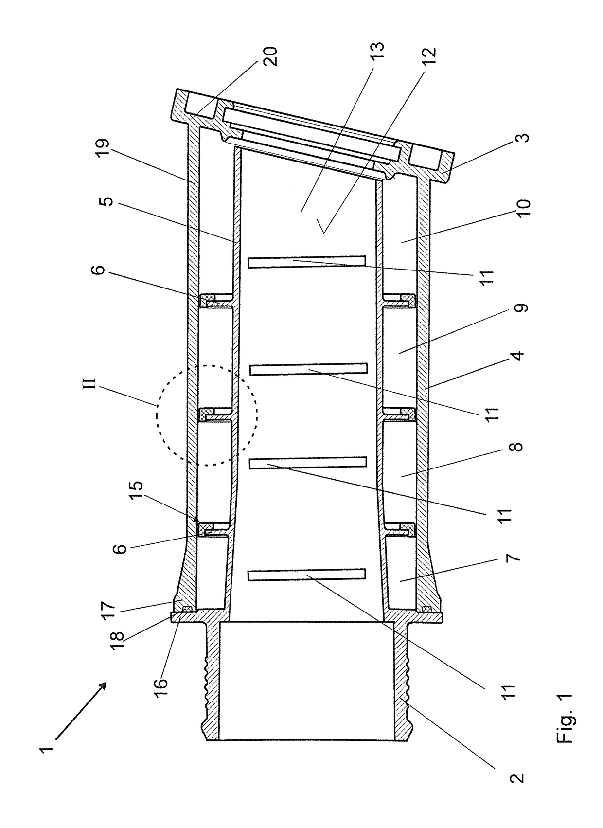
[0036]A device 1 for lowering flow noises (silencer) essentially comprises a first connection piece 2, a second connection piece 3, an outer sleeve 4 and an inner sleeve 5.

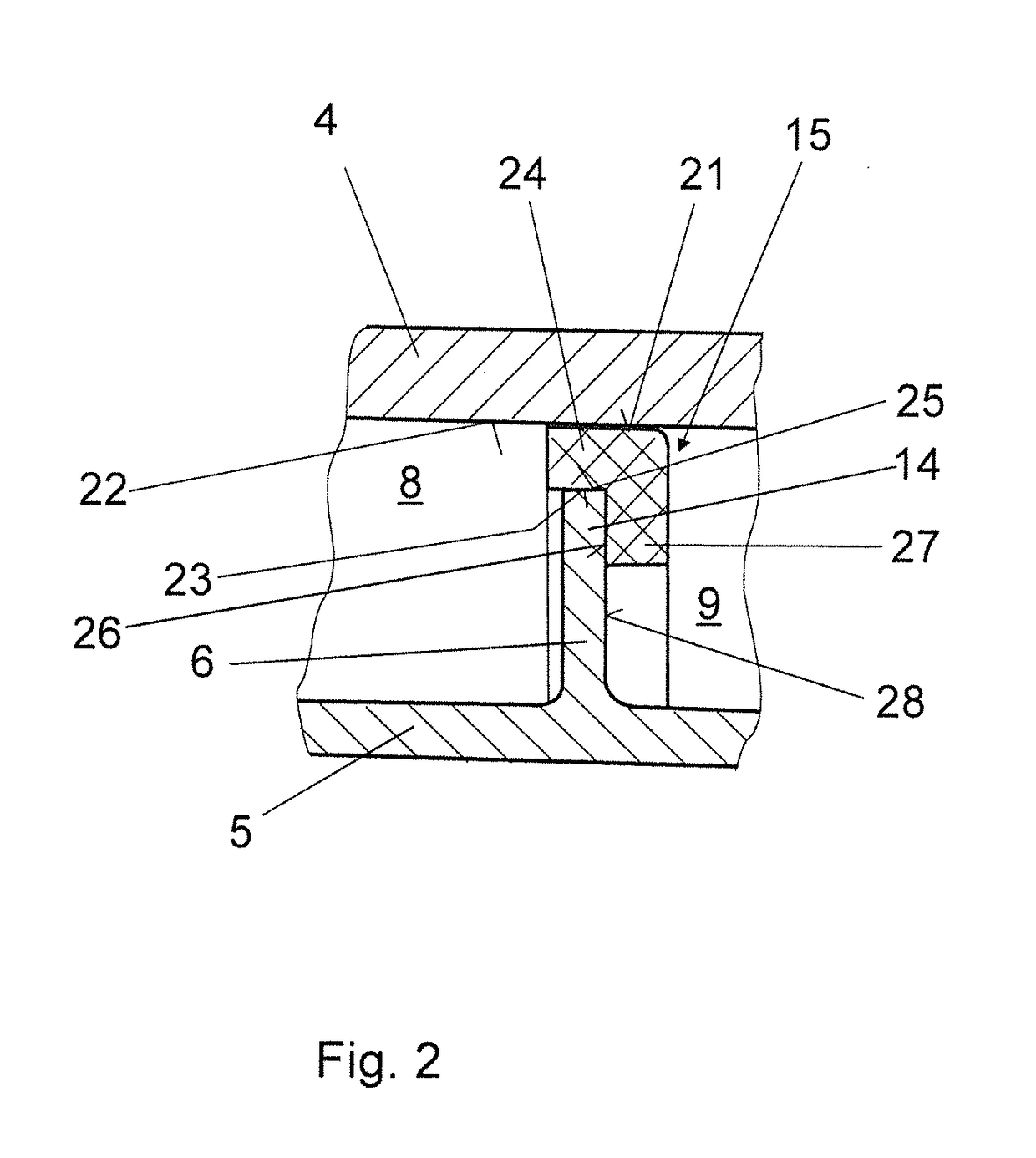
[0037]In the exemplary embodiments, the outer sleeve 4 and the inner sleeve 5 are arranged concentrically with respect to each other and between the first connection piece 2 and the second connection piece 3. In particular, the outer sleeve 4 can differ from the circular shape and can, for example, be constructed from two half shells (not shown). Between the inner sleeve 5 and the outer sleeve 4, in each case two adjacent volume chambers 7, 8, 9, 10 separated from each other by a peripherally extending radial collar 6 are arranged, said volume chambers being connected to the line space 13, which is enclosed by the inner sleeve 5, by means of openings 11 in the wall 12 of the inner sleeve 5. In the exemplary embodiments, the openings 11 are shown as slits. However, they can also be configured as holes, for example....


PUM


Abstract

A device (1) for lowering flow noises has opposed first and second connection pieces (2, 3), and outer and inner sleeves (4, 5) between the connection pieces. A radial collar (6) is between the sleeves (4, 5) and forms separated volume chambers. Openings (11) in the inner sleeve (5) connect the volume chambers to a line space (13) enclosed by the inner sleeve (5). A sealing ring (15) at the free end (14) of the collar (6) defines a ring cap with a lateral surface (21) that reaches over the collar (6) and seals against the sleeve (4, 5) adjacent the free end (14) of the collar (6) and that has a surface (23, 26) that seals against either an end face (25) of the collar (6) or a side surface (28) of the collar (6) extending parallel to the radial collar (6).

Description

BACKGROUNDField of the Invention[0001]The invention relates to a device for lowering flow noises, comprising a first connection piece, a second connection piece facing away from the first connection piece, an outer sleeve arranged between the first connection piece and the second connection piece, and an inner sleeve arranged between the connection pieces, wherein at least two volume chambers separated from each other by at least one peripherally extending radial collar are arranged between the inner sleeve and the outer sleeve, which volume chambers are connected to the line space enclosed by the inner sleeve by means of openings in the wall of the inner sleeve, wherein the radial collar has a sealing ring at the free end of the radial collar.Description of the Related Art[0002]When exhaust gas turbochargers, for example, are used in conjunction with internal combustion engines, undesirable flow noises result due to high engine speeds, unmanageable imbalances, disruptions due to pr...

Claims


Application Information

Patent Timeline
Patent Type & Authority Applications(United States)
IPC IPC(8): F02M35/12F02M35/10F16J15/10
CPCF02M35/1283F02M35/10144F16J15/102F02M35/10295F16J15/104F02M35/1266F16J15/022F16J15/0893F16L55/02781F16L55/033F02M35/10157Y02T10/12
Inventor BUCK, RALFHUER, MICHAELNAGEL, DIRKTROEGER, PHILIPPLUEBBE, NORBERT
Owner UMFOTEC
Why Eureka
Try Eureka