Three-dimensional imager having circular polarizers

a three-dimensional imager and circular polarizer technology, applied in the direction of distance measurement, instruments, using reradiation, etc., can solve the problems of inability to measure objects, tof scanners, and errors being determined

Inactive Publication Date: 2018-08-09
FARO TECH INC
View PDF5 Cites 21 Cited by
  • Summary
  • Abstract
  • Description
  • Claims
  • Application Information

AI Technical Summary

Benefits of technology

[0006]Accordingly, while existing 3D triangulation scanners and 3D TOF sca...

Problems solved by technology

A problem commonly encountered by triangulation scanners is multipath interference, which may result in erroneous values being determined 3D coordinates.
Another problem encountered by both triangulation scanners and TOF scanners is inability to measure objects because of a small amount of returned light, for example, because an object is ...

Method used


Image

  • Three-dimensional imager having circular polarizers
  • Three-dimensional imager having circular polarizers
  • Three-dimensional imager having circular polarizers

Examples


Embodiment Construction

[0076]Embodiments of the present invention provide advantages in recognizing and reducing or minimizing 3D errors from multipath interference. Embodiments further provides advantages in providing an ability to measure objects that return a relatively small amount of projected light, for example, because the object is nearly transparent or highly reflective. Embodiments further provide advantages in providing improved detail and accuracy in measured objects. Embodiments further provide advantages in more clearly displaying subtle features such as dents, scratches, chemical presence, and surface texture.

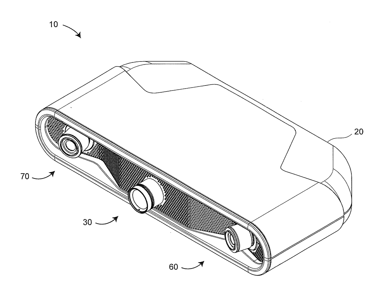
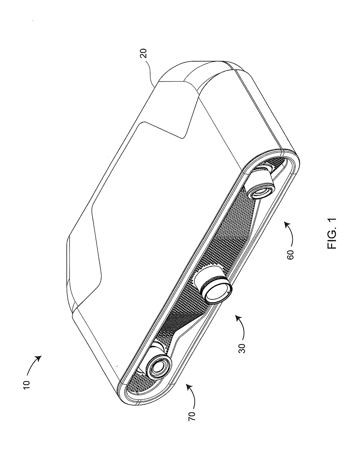
[0077]FIG. 1 is a perspective view of a triangulation scanner 10, also referred to as a 3D imager 10, according to an embodiment. It includes a frame 20, a projector 30, a first camera assembly 60, and a second camera assembly 70. In another embodiment, the 3D imager 10 includes only one camera rather than two cameras.

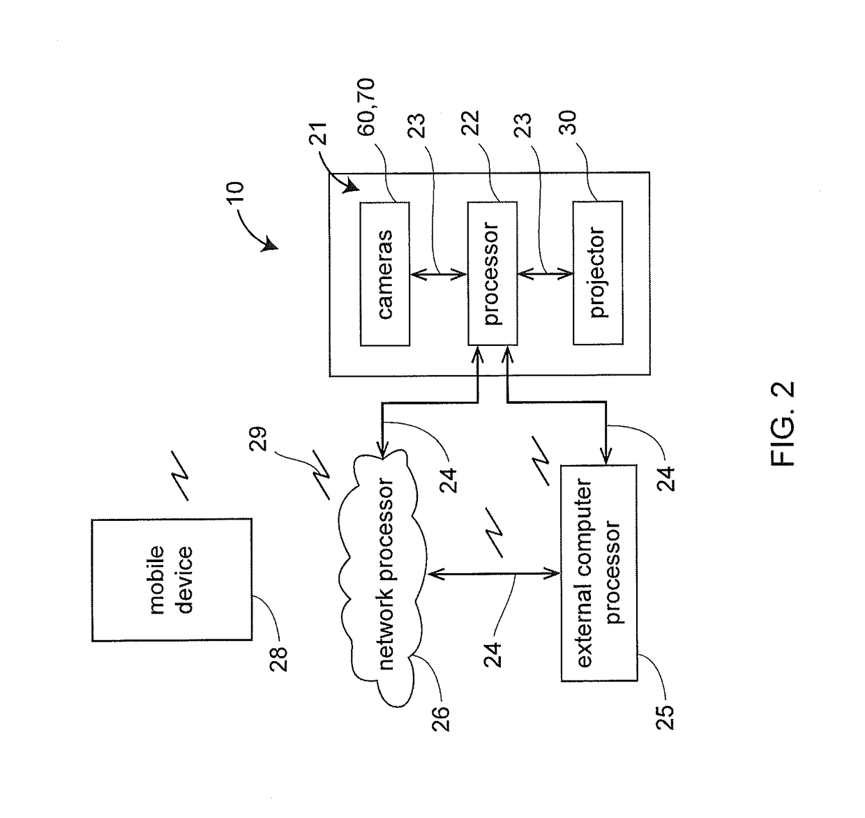
[0078]In an embodiment illustrated in FIG. 2, the 3D imager 10 inclu...


PUM


Abstract

A three-dimensional (3D) measuring system includes a triangulation scanner having a projector and a first triangulation camera, the projector including a first circular polarizer, the first triangulation camera including a second circular polarizer, the second circular polarizer having handedness opposite the first circular polarizer.

Description

CROSS REFERENCE TO RELATED APPLICATIONS[0001]This application claims the benefit of U.S. Provisional Application Ser. No. 62 / 455,839 filed Feb. 7, 2017, the entire disclosure of which is incorporated herein by reference.FIELD OF THE INVENTION[0002]The subject matter disclosed herein relates in general to a three-dimensional (3D) measuring device that use reflected light to measure 3D coordinates of objects.BACKGROUND[0003]One type of 3D measuring device is a triangulation scanner that uses a triangulation method to measure the 3D coordinates of points on an object. The triangulation scanner usually includes a projector that projects onto a surface of the object either a pattern of light in a line or a pattern of light covering an area. A camera is coupled to the projector in a fixed relationship, for example, by attaching a camera and the projector to a common frame. The light emitted from the projector is reflected off of the object surface and detected by the camera. Since the cam...

Claims


Application Information

Patent Timeline
IPC IPC(8): G01B11/25G06T7/73G02B27/28G01S17/48G01S7/486G01S7/4865G01S17/87G01S17/89
CPCG01B11/2545G06T7/73G02B27/28G01S17/48G01S7/4865G01B11/2531G06T7/521G01B11/2513G02B5/3025G02B27/288G02B26/023G01S17/66G01S17/87G01S17/89
Inventor WOLKE, MATTHIASHEIDEMANN, ROLFAMSTRONG, MATTHEW
Owner FARO TECH INC
Why Eureka
Try Eureka