Fitting connector

a technology of fitting connectors and connectors, applied in the direction of coupling devices, coupling devices with two parts, coupling device connections, etc., can solve problems such as workability at the time, and achieve the effect of preventing degradation of workability and increasing holding

Active Publication Date: 2018-08-09
YAZAKI CORP
View PDF0 Cites 16 Cited by
  • Summary
  • Abstract
  • Description
  • Claims
  • Application Information

AI Technical Summary

Benefits of technology

[0005]An object of the invention is to provide a fitting connector capable of increasing a holding force for keeping a completely fitted state and keeping the holding force while preventing degradation in workability at the time of inserting and extracting a connector.

Problems solved by technology

However, the fitting connector has concern that the workability at the time of inserting and extracting the connectors (the workability at the time of fitting the connectors or the workability at the time of releasing the fitted state between the connectors) may degrade in accordance with an increase in holding force.

Method used


Image

  • Fitting connector
  • Fitting connector
  • Fitting connector

Examples


embodiment

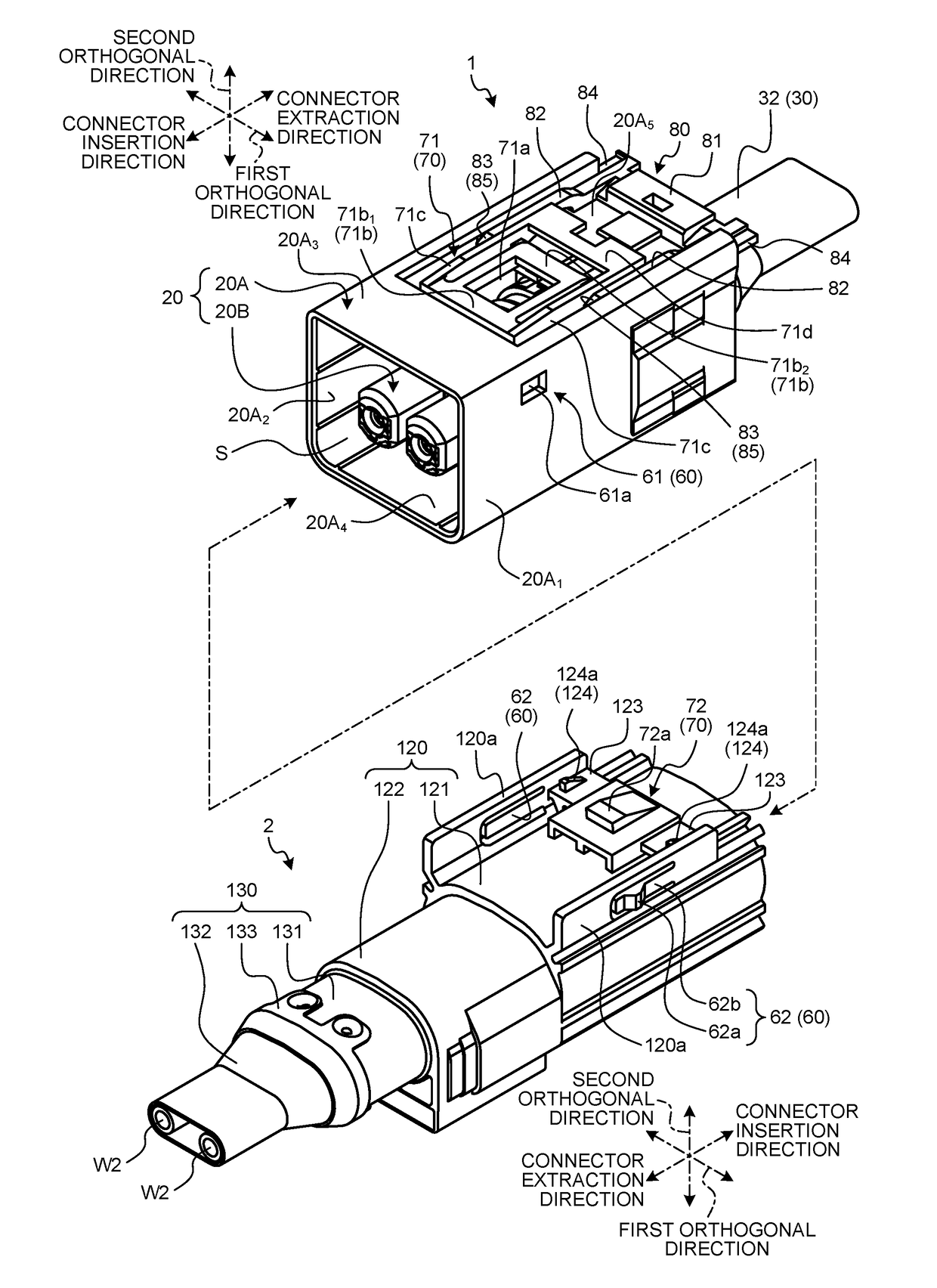
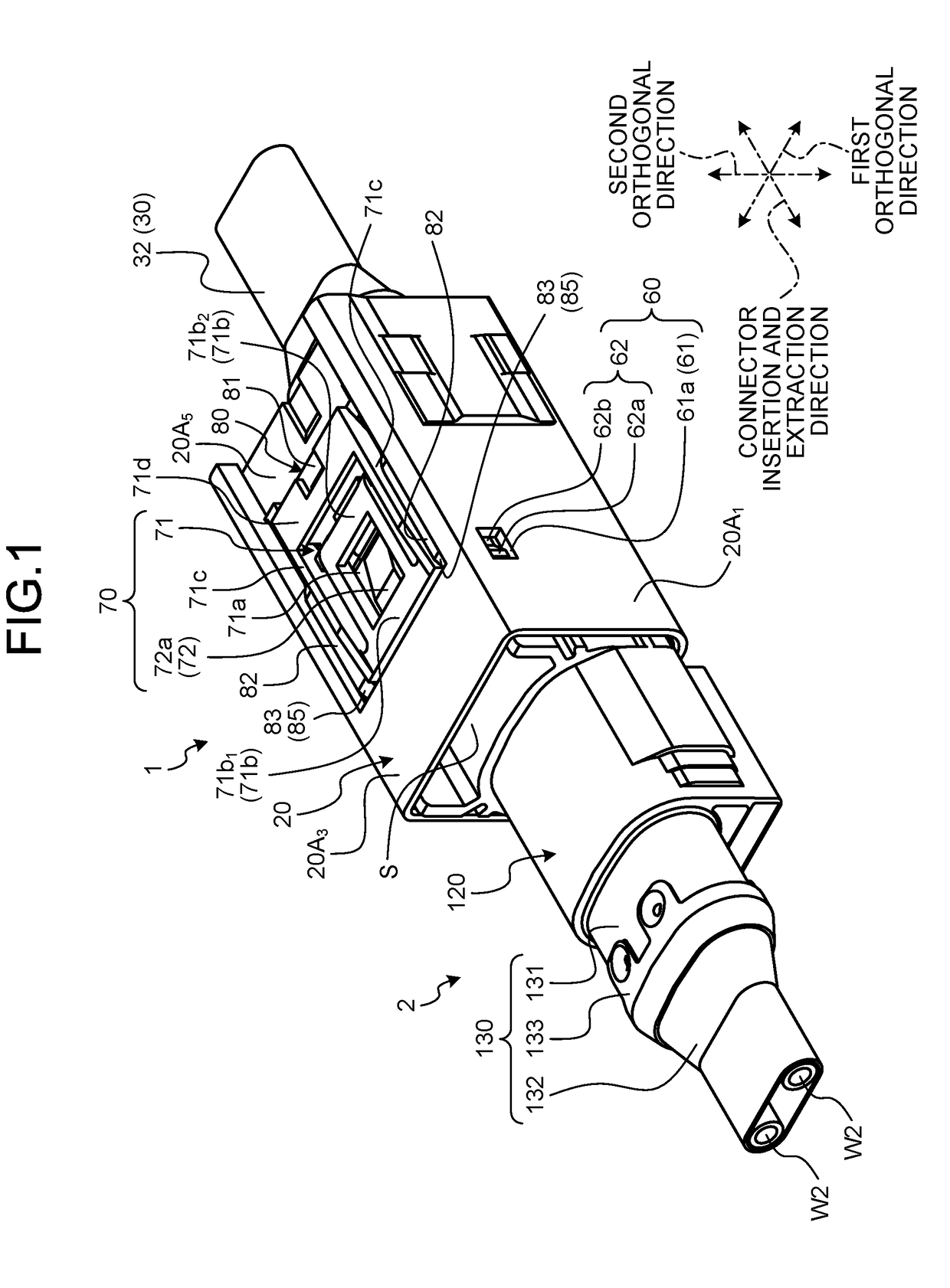
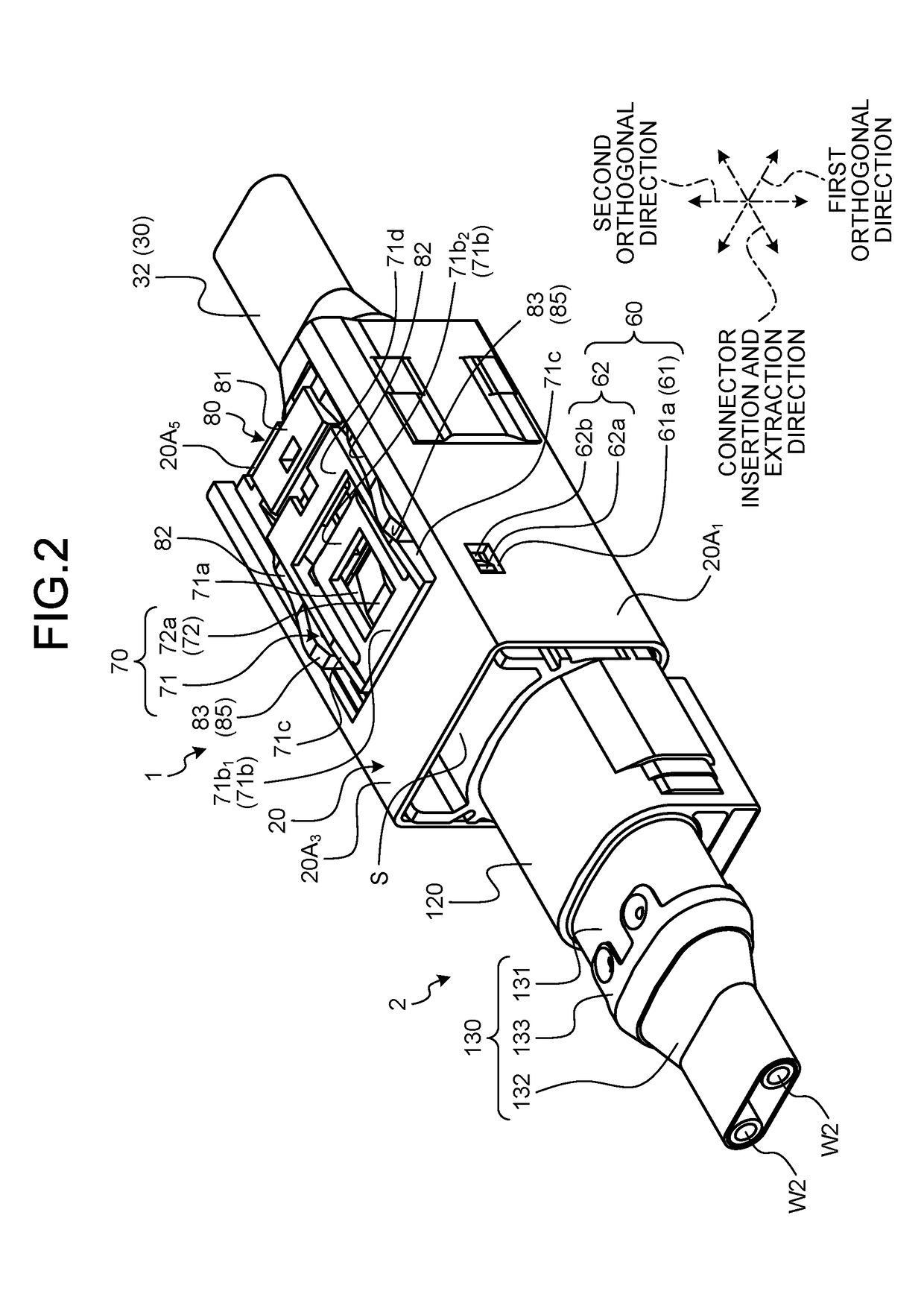
[0024]A fitting connector is provided with two connectors (a first connector and a second connector) which are fitted to each other. In the fitting connector, the first connector and the second connector are fitted to each other by a mutual insertion operation and both terminals are fitted to each other along with the fitting so that the terminals are physically and electrically connected to each other. Meanwhile, in the fitting connector, the first connector and the second connector are separated from each other by a mutual extraction operation and the physical and electrical connection between both terminals is released along with this operation. The insertion direction (the fitting direction) and the extraction direction are opposite directions. In the description below, the insertion direction will be referred to as a “connector insertion direction”, the fitting direction will be referred to as a “connector fitting direction”, and the extraction direction will be referred to as ...


PUM


Abstract

A fitting connector includes: a first connector; a second connector; a detection member that is relatively movable to a main locking position with respect to a housing when the housings are completely fitted to each other and is locked to the housing at the main locking position; and first and second holding structures which keep the completely fitted state, in which the first holding structure includes a first locking holder for the housing with a locking portion and a second locking holder provided in the counterpart housing and entering the locking portion to regulate the relative movement between the housings in the completely fitted state, in which the second locking holder includes a protrusion portion entering the locking portion and a flexible portion capable of moving the protrusion portion in a direction opposite to the insertion direction toward the locking portion while being bent.

Description

CROSS-REFERENCE TO RELATED APPLICATION(S)[0001]The present application claims priority to and incorporates by reference the entire contents of Japanese Patent Application No. 2017-019947 filed in Japan on Feb. 6, 2017.BACKGROUND OF THE INVENTION1. Field of the Invention[0002]The present invention relates to a fitting connector.2. Description of the Related Art[0003]Conventionally, there has been known a fitting connector including two connectors such as a female connector and a male connector to be fitted to each other and electrically connecting both terminals when the two connectors are fitted to each other. In the fitting connectors, a holding structure is provided between housings thereof to keep a fitted state between the housings of the connectors in a completely fitted state. The holding structure is used to keep the housings in the completely fitted state by engaging locking and holding portions respectively provided in the housings. For example, as the holding structure, a ...

Claims


Application Information

Patent Timeline
Patent Type & Authority Applications(United States)
IPC IPC(8): H01R13/627H01R13/641
CPCH01R13/6273H01R13/6272H01R13/641H01R13/6275H01R24/005
Inventor HAYASAKA, NOBORU
Owner YAZAKI CORP
Why Eureka
Try Eureka