Embroidery frame for use with embroidery sewing machine

a technology for embroidery sewing machines and embroidery frames, which is applied in the direction of embroidering machines, automatic machines, textiles and paper, etc., can solve the problems of increased production costs of clamp mechanisms, increased size, and complicated construction, and achieves the effect of simplifying the structure of each clamp mechanism

Active Publication Date: 2007-12-06
BROTHER KOGYO KK
View PDF19 Cites 14 Cited by
  • Summary
  • Abstract
  • Description
  • Claims
  • Application Information

AI Technical Summary

Benefits of technology

[0010]Therefore, an object of the disclosure is to provide an embroidery frame which is a clamp type that holds workpiece cloth between upper and lower frames and which can reliably hold workpiece cloths having various thicknesses and made from various materials while having a relatively simpler structure of each clamp mechanism.
[0012]In the above-described embroidery frame, the hold assisting member is attached to the cloth clamping side of either upper or lower frame. In this state, the workpiece cloth to be used for embroidery sewing can be held between the upper and lower frames. In this case, the hold of the workpiece cloth can be improved by the hold assisting member, whereupon the workpiece cloth can reliably be held. Moreover, no drive source such as an air cylinder is necessitated. Only provision of the hold assisting member can simplify the construction of the embroidery frame.
[0013]In one embodiment, the hold assisting member includes an engaging portion for the positioning thereof, and the lower frame has an engagement hole with which the engaging portion is engaged thereby to be held in position. When the hold assisting member is attached to the lower frame, the engaging portion thereof is caused to engage the engagement hole of the lower frame. Thus, the hold assisting member can reliably be attached to the lower frame by an easy operation without displacement. Furthermore, when the hold assisting member is to be detached from the lower frame, too, the engaging portion thereof is pulled out of the engagement hole of the lower frame. As a result, the hold assisting member can easily be detached from the lower frame.
[0014]In another embodiment, the hold assisting member is selected from plural hold assisting members which are formed into a thin plate shape and have different plate thicknesses. For example, when workpiece cloth to be held has a large thickness, a hold assisting member with a small thickness is selected. On the other hand, when workpiece cloth to be held has a small thickness, a hold assisting member with a large thickness is selected. Thus, the hold assisting member with a suitable thickness is selected according to the thickness of workpiece cloth. Consequently, a stable clamping force can be obtained with respect to workpiece cloths with various thicknesses.
[0015]In further another embodiment, the hold assisting member includes a thin base plate having elasticity and a holding member having a function of preventing the workpiece cloth from sliding. When the slip-proof holding member is disposed on the surface of the hold assisting member, the clamped workpiece cloth becomes hard to slide and accordingly, a holding performance can be improved. More specifically, the holding member may comprise a thin sheet-like pile including a piece of foundation cloth on which plural pieces of short fiber are transplanted. In the case where the thin sheet-like pile is employed as the holding member, the embroidery frame preferably has a predetermined embroidery-sewable region, and the short fiber is preferably formed so as to be inclined upward and so as to be directed outward from the embroidery-sewable region. Consequently, the held workpiece cloth becomes hard to displace inside the embroidery-sewable region (inner region of the embroidery frame) and accordingly more effective.
[0019]In the above-described embroidery frame, the workpiece cloth can be held between the upper and lower frames with the slide-proof holding member being provided on the cloth holding surface of the upper frame. In this case, the holding member can improve the hold of the workpiece cloth such that the workpiece cloth can reliably be held. Moreover, no drive source such as an air cylinder is necessitated. Only provision of the hold assisting member can simplify the construction of the embroidery frame. Additionally, since the upper frame is detachably attached to the clamp mechanism, the upper frame can be replaced by another according to the thickness or material of the workpiece cloth.

Problems solved by technology

Thus, the provision of the air cylinders results in a complicated construction, increased size and increased production cost of the clamp mechanism.
However, in the case where the spring force is used to press the upper frame against the lower frame, an amount of flexure is increased when workpiece cloth has a large thickness, whereupon a sufficient spring force can be obtained.
On the other hand, the spring force is small when workpiece cloth has a small thickness, whereupon a sufficient holding force cannot be obtained.
In particular, when workpiece cloth is made from a slippery material, there is a possibility that the workpiece cloth may be displaced within the embroidery frame and accordingly, cannot be embroidered desirably.
Moreover, no drive source such as an air cylinder is necessitated.

Method used


Image

  • Embroidery frame for use with embroidery sewing machine
  • Embroidery frame for use with embroidery sewing machine
  • Embroidery frame for use with embroidery sewing machine

Examples


Embodiment Construction

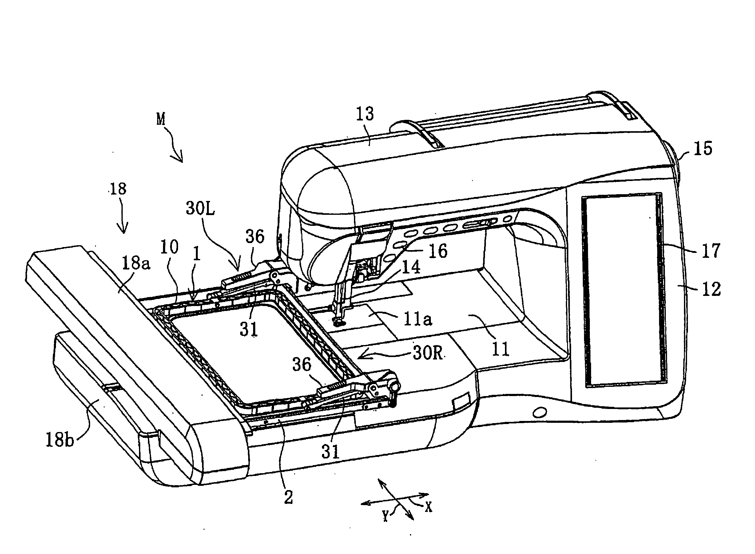
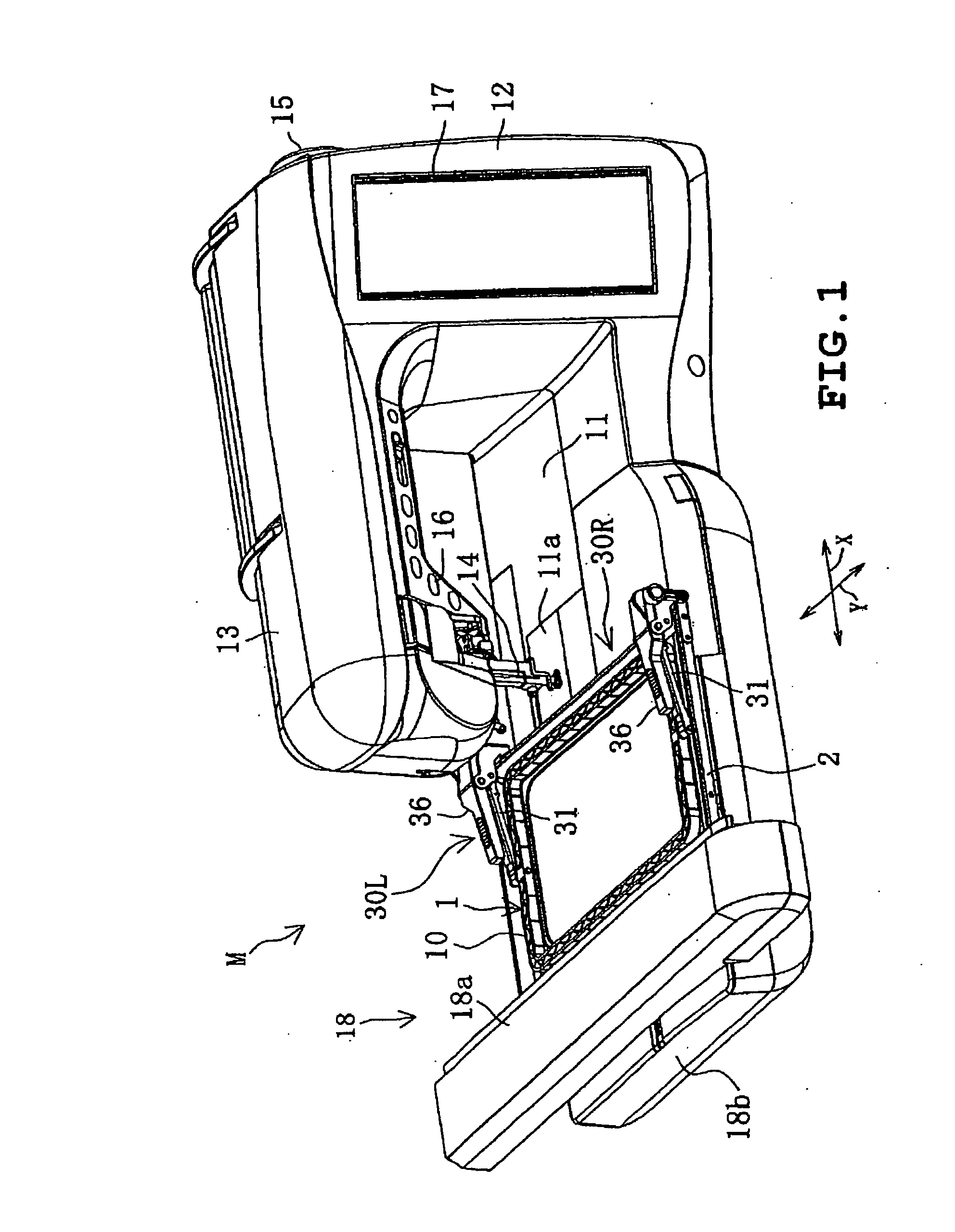
[0034]A first illustrative example of the disclosure will be described with reference to FIGS. 1 to 7. The disclosure is applied to an embroidery frame for use with an electronic sewing machine. Referring to FIG. 1, an overall electronic sewing machine M which is capable of performing embroidery sewing is shown. The electronic sewing machine M includes a sewing bed 11 extending in the right-and-left direction (the X direction), a sewing pillar 12 rising upward from a right end of the bed 11 and a sewing arm 13 extending leftward from an upper end of the pillar 12, all of which are formed integrally.

[0035]The arm 13 has a distal end including a lower part on which a needle bar with a sewing needle 14 is mounted. The bed 11 has a top on which a needle plate 11a is mounted so as to correspond to the sewing needle 14. The bed 11 encloses therein a full rotary hook which forms stitches in cooperation with the sewing needle 14, a feed dog forward / backward moving mechanism and a thread cut...


PUM

PropertyMeasurementUnit
thicknessesaaaaaaaaaa
elasticityaaaaaaaaaa

Abstract

An embroidery frame holding workpiece cloth for embroidery sewing includes a lower frame receiving a lower side of the workpiece cloth and having a cloth clamping side, an upper frame holding the workpiece cloth in cooperation with the lower frame between the frames and having a cloth holding side, a clamp mechanism pressing the upper frame against the lower frame and retaining the upper frame in a pressing state, and a hold assisting member enhancing hold of the workpiece cloth and detachably attached to the cloth holding side of at least one of the upper and lower frames.

Description

CROSS-REFERENCE TO RELATED APPLICATIONS[0001]This application is based upon and claims the benefit of priority from the prior Japanese Patent Application No. 2006-154440 filed on Jun. 2, 2006, the entire contents of which are incorporated herein by reference.BACKGROUND[0002]1. Technical Field[0003]The present disclosure relates to embroidery frames for use with embroidery sewing machines, and more particularly to such an embroidery frame including upper and lower frames between which workpiece cloth is held and a clamp mechanism pressing the upper frame against the lower frame and retaining the upper frame in the pressing state.[0004]2. Description of the Related Art[0005]In conventional sewing machines capable of performing embroidery sewing, workpiece cloth to be embroidered is held in a tightly stretched state by an embroidery frame detachably attached thereto. Conventional embroidery frames include a type in which outer and inner frames are connected together and disconnected fr...

Claims


Application Information

Patent Timeline
Patent Type & Authority Applications(United States)
IPC IPC(8): D05C9/04D05C7/04
CPCD05C9/04D05B39/00
Inventor WATANABE, YASUHIRO
Owner BROTHER KOGYO KK
Why Eureka
Try Eureka