Heat exchanger

a heat exchanger and heat exchanger technology, applied in the field of heat exchangers, can solve the problems of unstable available connecting techniques, inability to integrate the heat exchanger into the heat exchanger, and inefficiency of conventional heat exchangers, so as to reduce production costs, improve heat transfer, and increase distance

Inactive Publication Date: 2012-12-27
BEHR GMBH & CO KG
View PDF3 Cites 14 Cited by
  • Summary
  • Abstract
  • Description
  • Claims
  • Application Information

AI Technical Summary

Benefits of technology

[0016]The profiling may be designed in the form of a plurality of elongated raised structures. The plurality of raised structures may be disposed on the guide sheet in such a way that a meandering guidance for the second medium around multiple tubes is made possible. For example the elongated raised structures may be designed as narrow, elongated knobs between two diagonally opposite tubes from two different rows of tubes disposed in parallel alignment. In this manner, the second medium may be advantageously guided or deflected along the outer wall of the tube, which makes it possible to achieve a better heat transfer with the first medium carried in the inner tube.
[0017]According to another embodiment, the guide sheet may have a profiling in the form of a plurality of protrusions. The guide sheet may be disposed adjacent to at least one additional guide sheet which has a profiling in the form of a plurality of protrusions, multiple protrusions of the profiling of the guide sheet being able to engage on the back with corresponding protrusions of the profiling of the additional guide sheet. A fixing of multiple, stacked guide sheets to each other, and thus also an improved hold for multiple tubes which engage with the stack of guide sheets, may thus be favorably provided.
[0018]Alternatively, the guide sheet may be disposed adjacent to at least one additional guide sheet having a profiling, the profiling of the guide sheet and the profiling of the additional guide sheet having the same structure and being able to face the same raising direction, the other guide sheet, however, being able to be rotated 180 degrees with regard to a normal to the guide sheet. According to this specific embodiment, therefore, the profiling of two adjacent guide sheets having identical profiling may be prevented from engaging with each other, since, for example, a distance between the guide sheets would thus be too small for certain applications or application scenarios of the heat exchanger. Since it is possible to dispense with the manufacture of differently profiled guide sheets, however, production costs may be reduced in this type of configuration of the guide sheets, since only guide sheets of the same type need to be manufactured.
[0019]The guide sheet may also be disposed adjacent to at least one additional guide sheet having a profiling, the profiling of the guide sheet and the profiling of the additional guide sheet being able to face each other. In a stack of guide sheets, therefore, two surfaces having profiling and two upper sides not having profiling may each alternately face each other. This provides the advantage that the raised structures of the profiling of both guide sheets may touch each other and thereby ensure a greater distance between the two guide sheets. For certain application scenarios, in particular for two media of higher viscosity, such a greater distance between the guide sheets may be helpful to ensure a lower resistance of the second medium between the guide sheets.
[0020]According to another embodiment, the at least one guide sheet may be uneven in the area of the passages in the tube or uneven in the area of the at least one recess. For example, the guide sheet may be corrugated in the area of the recesses. This specific embodiment of the guide sheet offers the advantage, on the one hand, that an improved hold for the at least one tube may be achieved without additional components, since a larger area of the tube is contacted and held by the guide sheet, due to the uneven form. On the other hand, an improved heat transfer may be made possible between the guide sheet and the tube, since a greater contact line exists between the uneven guide sheet and the tube.

Problems solved by technology

Conventional TEGs are not very efficient, due to the elevated heat transfer resistance between thermoelectrically active materials and a heat source / heat sink.
Integrating the TEM into a heat exchanger has also proven to be not very practical.
Up to now, available connecting techniques have been, in part, unstable at high temperatures.
In addition, only minimal heat transfer frequently exists on the contacting of the TEM in the heat exchanger on the gas side.
According to the prior art, conventional TEMs are therefore not optimally suited for use in a TEG, due to their design and connecting techniques, and are also not very effective.

Method used


Image

  • Heat exchanger
  • Heat exchanger
  • Heat exchanger

Examples


Embodiment Construction

[0050]In the following description of the exemplary embodiments of the present invention, identical or similar reference numerals are used for the elements illustrated in the different drawings and having a similar function, these elements not being described repeatedly.

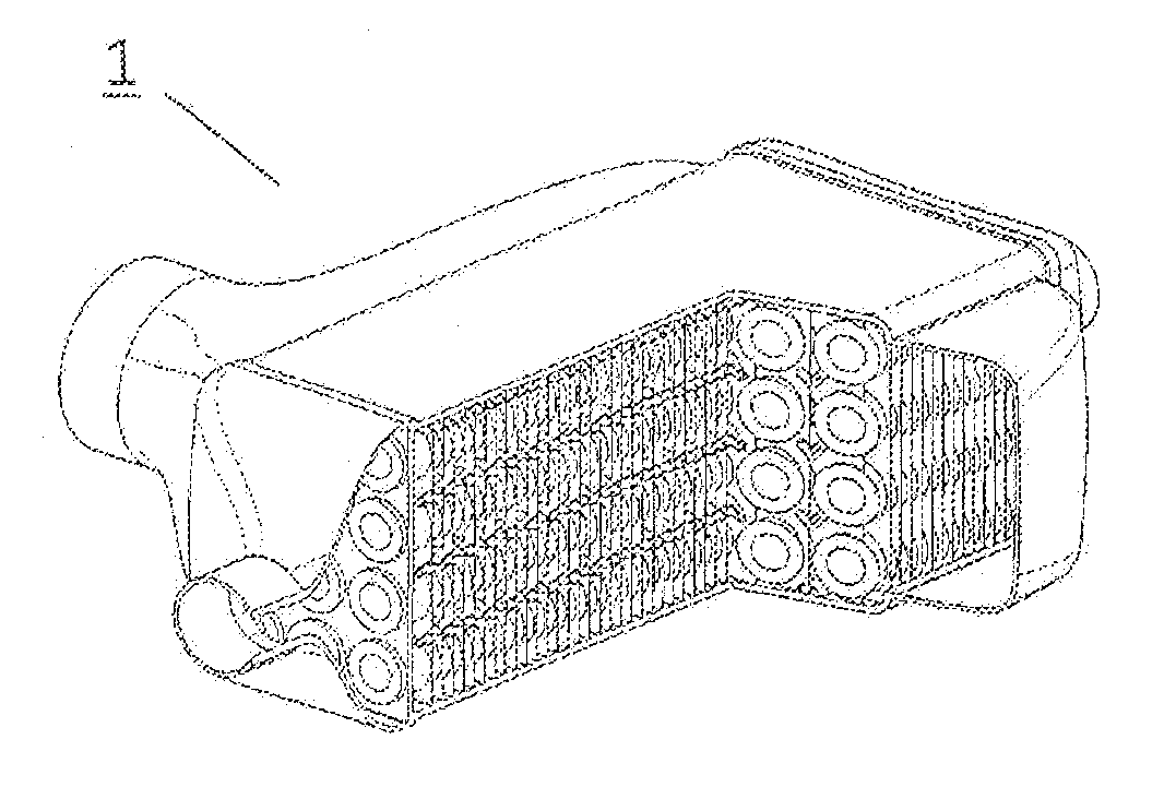
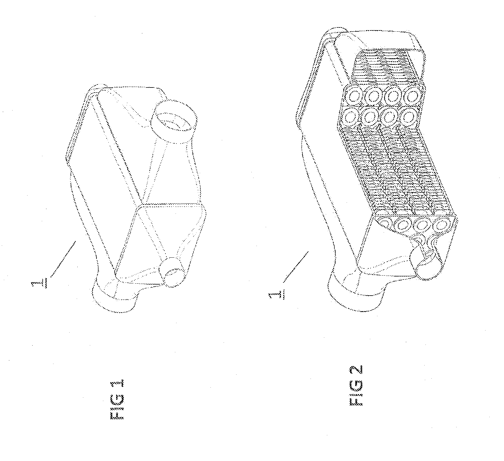
[0051]The heat exchanger according to the invention may be used, for example, as a thermoelectric generator (TEG) for generating electricity in a vehicle.

[0052]In a TEG according to exemplary embodiments of the invention, two media of different temperatures may be conducted past each other in a cross flow along a heat transfer route, so that heat may be transferred from the warm medium to the cold medium. The two media are separated to prevent mixing from occurring. The hot medium is, for example, exhaust gas, and the cold medium is, for example, a water / Glysantin mixture, which may be used as a coolant. The exhaust gas comes from, for example, an internal combustion engine; the water / Glysantin mixture comes from a c...


PUM


Abstract

A heat exchanger for exchanging heat between two media in a vehicle is provided. The heat exchanger includes at least one tube, especially a double-walled tube for carrying a first medium of a first temperature, a thermoelectric material being disposed on an inner wall of the tube, and at least one guide sheet, connected to the at least one tube, for carrying a second medium of a second temperature. The at least one guide sheet is designed to carry the second medium to the outer wall of the at least one tube to allow the exchange of heat between the first and the second medium.

Description

[0001]This nonprovisional application is a continuation of International Application No. PCT / EP2010 / 069107, which was filed on Dec. 7, 2010, and which claims priority to German Patent Application No. DE 10 2009 058 676.8, which was filed in Germany on Dec. 16, 2009, and which are both herein incorporated by reference.BACKGROUND OF THE INVENTION[0002]1. Field of the Invention[0003]The present invention relates to a heat exchanger for exchanging heat between two media, as used, for example in a vehicle.[0004]2. Description of the Background Art[0005]The energy which is stored, for example, in the exhaust gas of a vehicle in the form of heat, is currently unused and discharged into the surroundings. To increase the efficiency of a system, e.g., a motor vehicle, and consequently reduce CO2 emissions during operation, a thermoelectric generator (TEG) may be implemented whose thermoelectric module (TEM) converts part of the heat to electrical energy and returns it to the system. The TEG i...

Claims


Application Information

Patent Timeline
Patent Type & Authority Applications(United States)
IPC IPC(8): F25B21/02
CPCF01N3/043F01N5/025F28D7/1653F28D7/1684F28F1/32F28F3/044F28F2240/00F28F2001/027H01L35/30Y02T10/16Y02T10/20F28F2215/10F28F13/06Y02T10/12H10N10/13
Inventor BREHM, HOLGERHECKENBERGER, THOMASHIMMER, THOMASLARPENT, STEPHANIEPATERSON, JULIERIEDEL, RUDOLF
Owner BEHR GMBH & CO KG
Why Eureka
Try Eureka