Haying machine

a technology of haying machine and latching means, which is applied in the direction of couplings, ploughs, applications, etc., can solve the problems of compromising safety during travel, heavy weight and difficult maneuverability, and intense stress, and achieves the effect of reducing the stress on the latching means, reducing costs, and improving safety

Inactive Publication Date: 2006-09-05
KUHN SA
View PDF16 Cites 14 Cited by
  • Summary
  • Abstract
  • Description
  • Claims
  • Application Information

AI Technical Summary

Benefits of technology

[0008]This disposition of the latching means on the carrying arms allows them to be distant from the frame and the axes of articulation of said arms on the frame. They may for example be situated at a distance from said axes which is at least equal to half the length of the carrying arms when they are in transport position. The stresses that are exerted on the latching means are then considerably reduced. The hold of these latching means and the safety are thus improved. In addition, these means can be simple and less costly.

Problems solved by technology

When the machine travels over unevennesses, they are subject to intense stresses due to the forces exerted on them by the carrying arms with considerable lever arms.
These latches therefore have to be particularly strong, which makes them bulky and difficult to maneuver.
In addition, they suffer heavy wear which can rapidly compromise safety during travel.

Method used


Image

  • Haying machine
  • Haying machine
  • Haying machine

Examples


Embodiment Construction

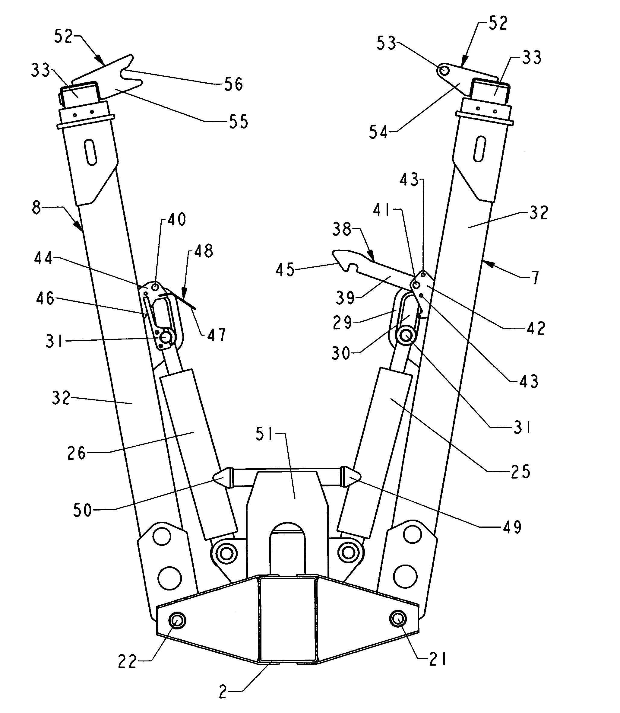
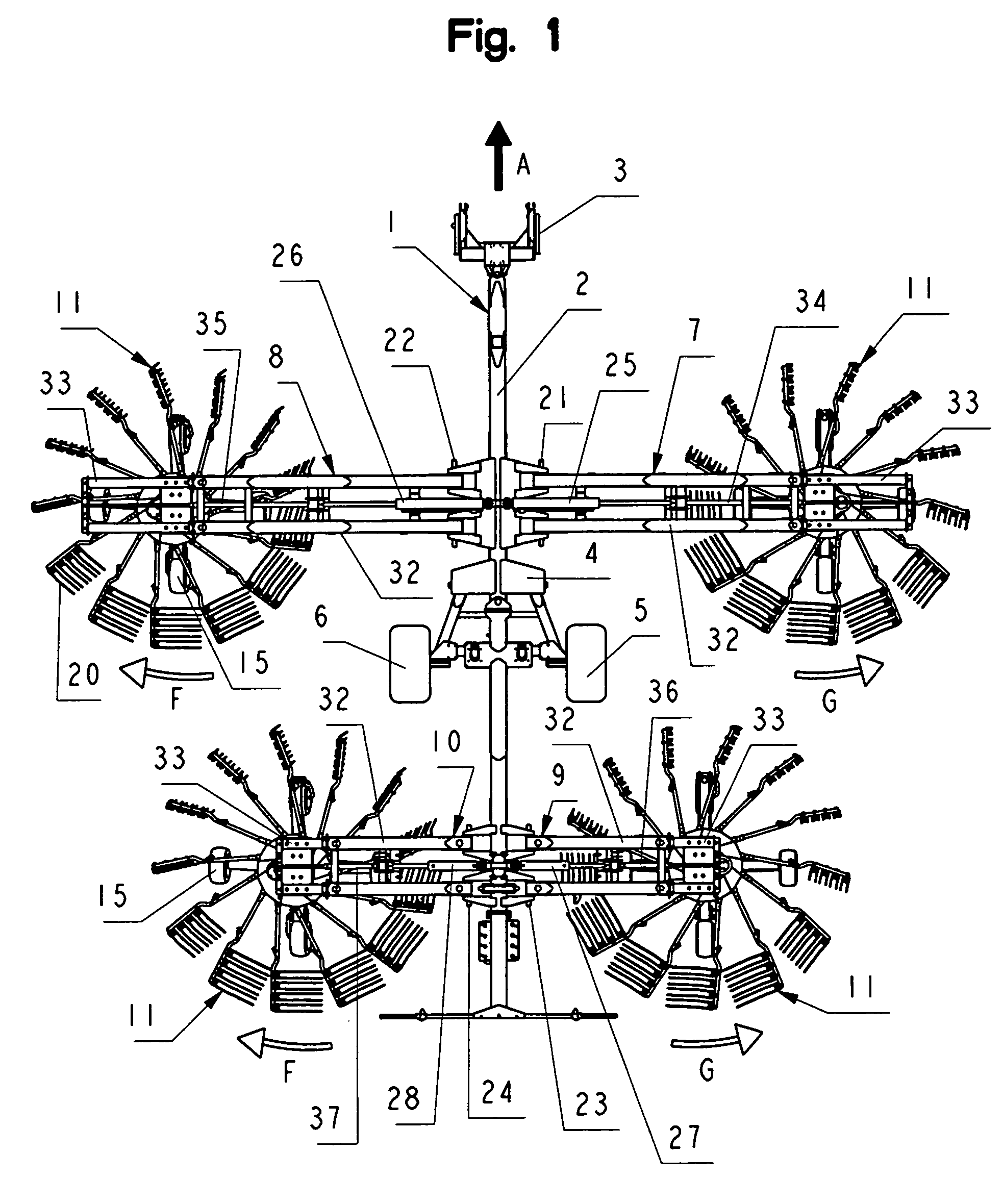
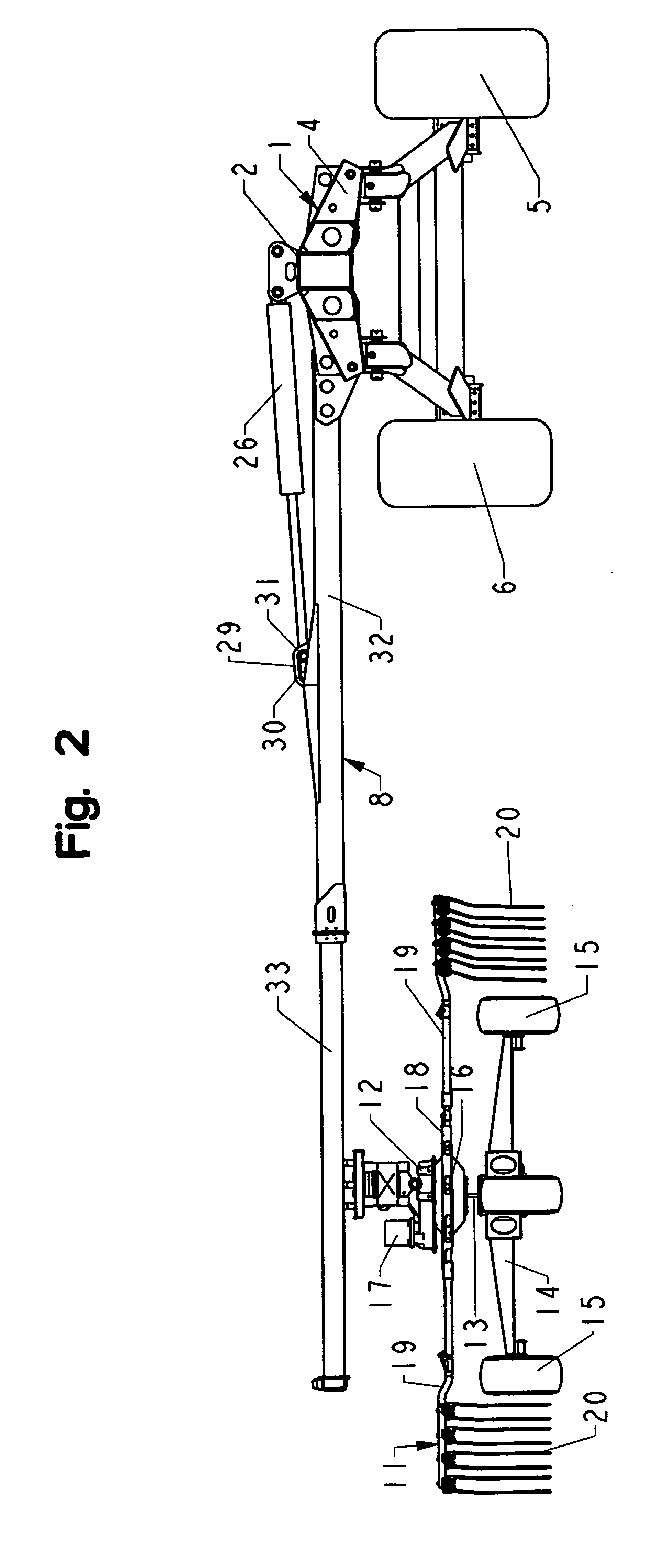
[0016]As is represented in figures 1 and 2, the machine according to the invention comprises a frame (1). This consists of a central beam (2) which has at its front end a coupling device (3) for attaching it to a driving tractor and, at the rear of said device (3), a support (4) with two traveling wheels (5 and 6) which rest on the ground. The frame (1) also comprises four arms (7, 8, 9 and 10) each carrying one rotor (11) intended to windrow products such as mown grass or straw spread on the ground. These arms (7 to 10) are disposed in pairs, one of which is situated forward of the central beam (2) and the other rearward of the latter. The two carrying arms (7 and 8, 9 and 10) of each pair are situated substantially in one and the same plane perpendicular to the direction of travel (A), one on the right and the other on the left of the beam (2). The number of pairs of rotors (11) and pairs of carrying arms (7 to 10) may vary according to the working width of the machine.

[0017]Each ...


PUM


Abstract

A haymaking machine including a frame carrying at least one pair of rotors connected to carrying arms that may be moved from a working position, in which they are substantially horizontal, to a transport position, in which they are substantially vertical, and vice-versa. The carrying arms of at least one pair of rotors include a latching mechanism that connects them together and locks them with regard to one another in the transport position.

Description

BACKGROUND OF THE INVENTION[0001]1. Field of the Invention[0002]The present invention relates to a haymaking machine, particularly for windrowing forage, comprising a frame carrying at least one pair of windrowing rotors that can be driven in rotation about substantially vertical supporting axes, which rotors are connected to carrying arms which are situated substantially in one and the same plane perpendicular to the direction of travel, the one on the right and the other on the left of the frame and which are articulated on said frame by means of axes of articulation about which they can be moved from a working position, in which they are substantially horizontal, to a transport position, in which they are substantially vertical, and vice-versa, by means of hydraulic jacks.[0003]Placing the carrying arms and the rotors in a substantially vertical position makes it possible to considerably reduce the width of the machine. This allows it to be easily moved on public roads. In this p...

Claims


Application Information

Patent Timeline
Patent Type & Authority Patents(United States)
IPC IPC(8): A01D76/00A01D78/00A01D80/00A01D84/00A01D78/10
CPCA01D78/1007Y10T403/593A01D78/1014
Inventor BRENEUR, DAVID
Owner KUHN SA
Why Eureka
Try Eureka