Device for protecting a tire wall

a technology for protecting a tire wall and a sidewall, which is applied in the field of tires, can solve the problems of rubber material present between the cords, damage to one sidewall, and damage to the tire wall of heavy-duty vehicles

Active Publication Date: 2018-08-16
MICHELIN & CO CIE GEN DES ESTAB MICHELIN
View PDF9 Cites 3 Cited by
  • Summary
  • Abstract
  • Description
  • Claims
  • Application Information

AI Technical Summary

Benefits of technology

[0015]The present disclosure seeks to provide a tire of which at least one sidewall is protected from the external attack suffered by one of the sidewalls of the tire upon contact with an obstacle when this tire is running. This contact may manifest itself in a violent load having a component directed in a direction pointing toward the inside of the internal cavity of the tire and another component directed in a circumferential direction.

Problems solved by technology

It is known that tires for heavy duty vehicles, notably those used on poor-quality road networks, may experience attack when running or maneuvering.
These same tires may also, when running in town, come into contact with kerbs which under certain conditions can be harmful and damage one of the sidewalls.
These attacks may have the consequence of violently stress-loading the carcass and crown reinforcements or may even go so far as to cause the rubber material present between the cords of the carcass reinforcement to break, with all the resulting consequences that may be imagined, notably loss of tire pressure.
These same attacks, without causing breakages at the moment of contact, may affect the ability of the tire to withstand repeated bending loadings; that is because of the high deformations suffered by the materials at the moment of contact with an obstacle.
When running on roads comprising obstacles or various objects, it may happen that the sidewalls are subjected to external attack from these obstacles or these objects.
While the majority of such attacks have little influence on the integrity of the sidewalls, breaks may however appear in the loaded sidewall.
That is of course highly prejudicial to tire lifetime because the sidewalls often cannot be repaired, the breakages spreading between the cords of the carcass reinforcement reinforcing the sidewalls.
This problem is known and solutions have already been proposed, but it would seem that none of the known solutions is fully satisfactory.

Method used


Image

  • Device for protecting a tire wall
  • Device for protecting a tire wall
  • Device for protecting a tire wall

Examples


Embodiment Construction

[0034]To make the figures easier to read, the same reference signs have been used for describing alternative forms of the disclosure where these reference signs refer to elements that are the same in nature whether structurally or indeed functionally.

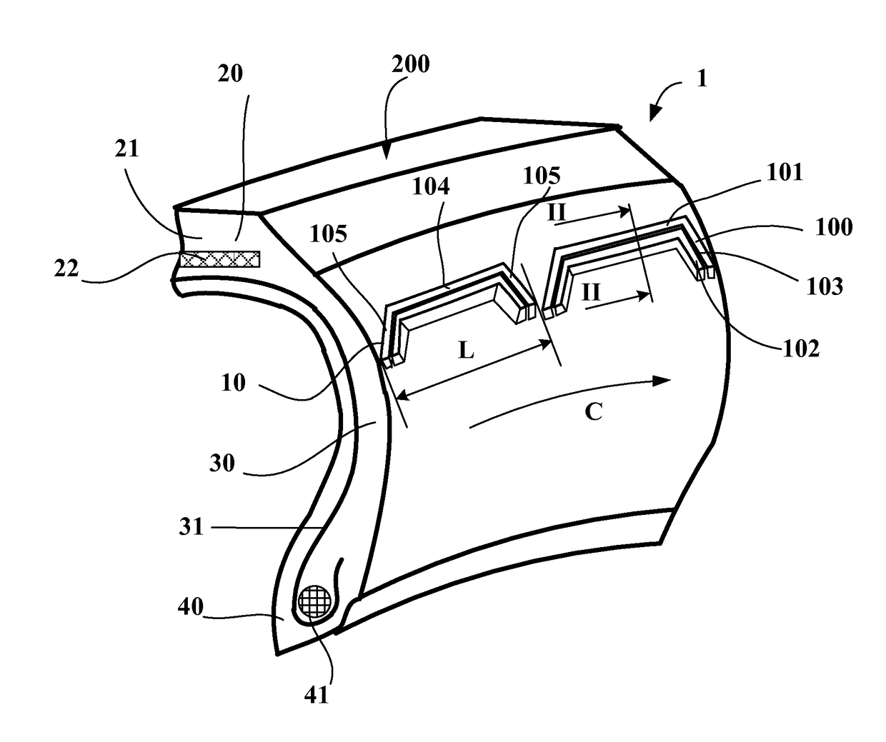
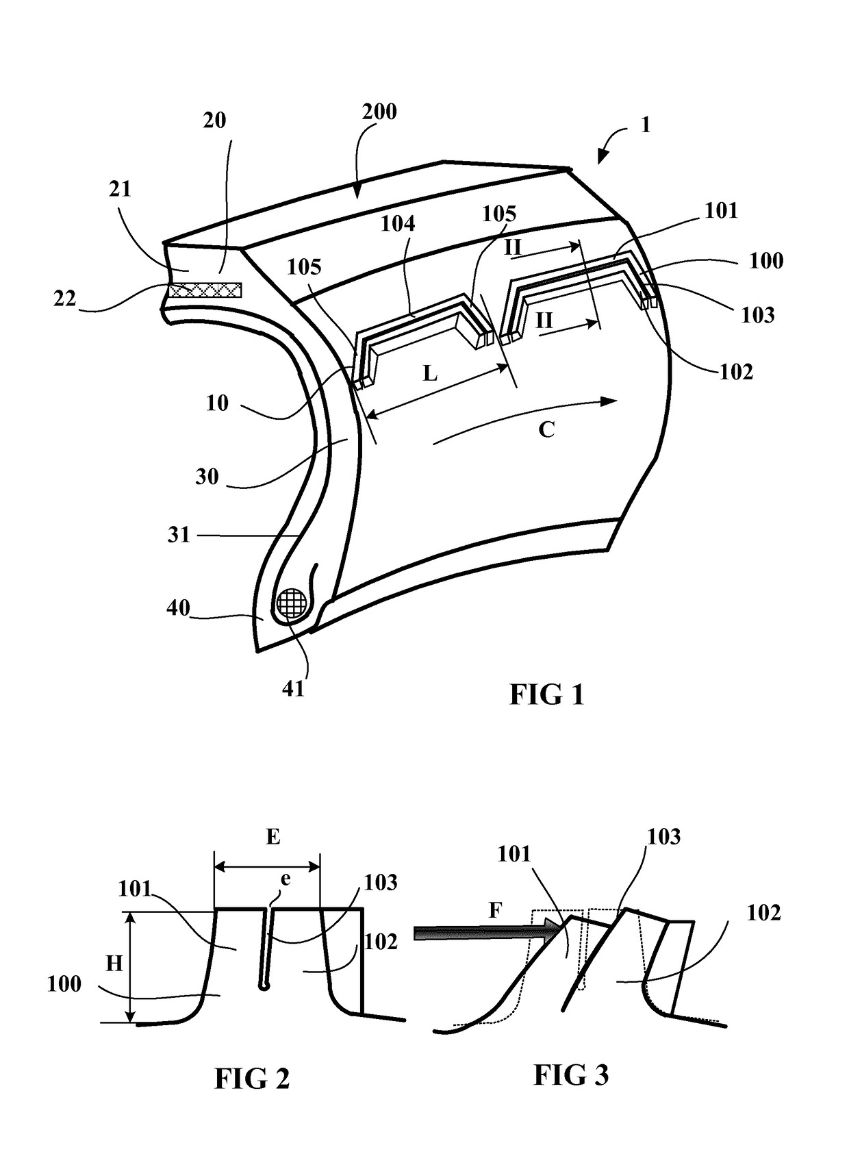
[0035]FIG. 1 depicts a perspective view of part of a tire 1 comprising a sidewall protection device according to a first alternative form of the disclosure. The tire 1 shown comprises a crown part 20 extended on each side by sidewalls 30, these sidewalls 30 connecting to beads 40 intended to come into contact with a tire mounting rim (not depicted here).

[0036]The tire 1 is reinforced by a carcass reinforcement 31 made up of a plurality of reinforcers. In this instance, these reinforcers are anchored in each bead 40 on bead wires 41 and extend from bead to bead passing through the sidewalls and the crown part 20.

[0037]In the case described, only the sidewall 30 intended to be positioned such that it is visible from the outside of the veh...


PUM


Abstract

The tire comprises a carcass reinforcement which extends into sidewalls. The tire is also provided with a protection device that protects against external attack. The protection device comprises a plurality of raised elements of height H that are arranged in the circumferential direction. The tire is also constructed such that each raised element is formed of at least two parts which are at least partially disjointed from one another along a separation zone. The separation zone is oriented substantially in the circumferential direction. Each part is able to come into contact with another part of the same raised element when one of the parts comes into contact with an external obstacle.

Description

CROSS-REFERENCE TO RELATED APPLICATION[0001]The present invention claims priority to PCT International Patent Application Serial No. PCT / EP2015 / 073971 filed Oct. 16, 2015 entitled “Device For Protecting A Tire Wall,” which claims the benefit of FR Patent Application Serial No. 1460119 filed Oct. 21, 2014, the entire disclosures of the applications being considered part of the disclosure of this application and hereby incorporated by reference.BACKGROUND OF THE INVENTION1. Field of the Invention[0002]The present invention relates to tires of vehicles that are heavily loaded such as the tires intended to be fitted to heavy duty vehicles. It relates more particularly to a device for protecting these tires against potential attacks suffered by the sidewalls of these tires.2. Related Art[0003]A tire for a heavy duty vehicle comprises beads intended to come into contact with a mounting rim, sidewalls and a crown. The crown of the tire comprises a reinforcing reinforcement surmounted radia...

Claims


Application Information

Patent Timeline
Patent Type & Authority Applications(United States)
IPC IPC(8): B60C13/00B60C19/12
CPCB60C13/002B60C19/12B60C2200/06B60C13/02
Inventor BUFFETAUD, BENOITGODEAU, GILLESLAPRA, LAURENCEVANDAELE, MATHIEU
Owner MICHELIN & CO CIE GEN DES ESTAB MICHELIN
Why Eureka
Try Eureka