

Longitudinal arm of torsion beam suspension frame and torsion beam suspension frame
A technology of torsion beam and trailing arm, used in suspension, elastic suspension, transportation and packaging, etc., can solve the problem of easy tearing of lap welds, achieve less cracking, reduce the number of welds, and increase the strength of the force. Effect
- Summary
- Abstract
- Description
- Claims
- Application Information
AI Technical Summary
Problems solved by technology
Method used
Image

Examples
Embodiment Construction
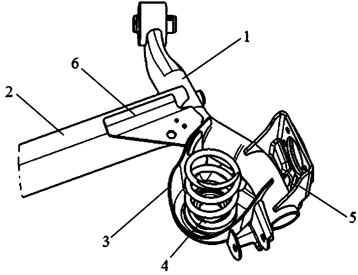
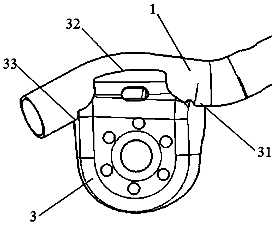
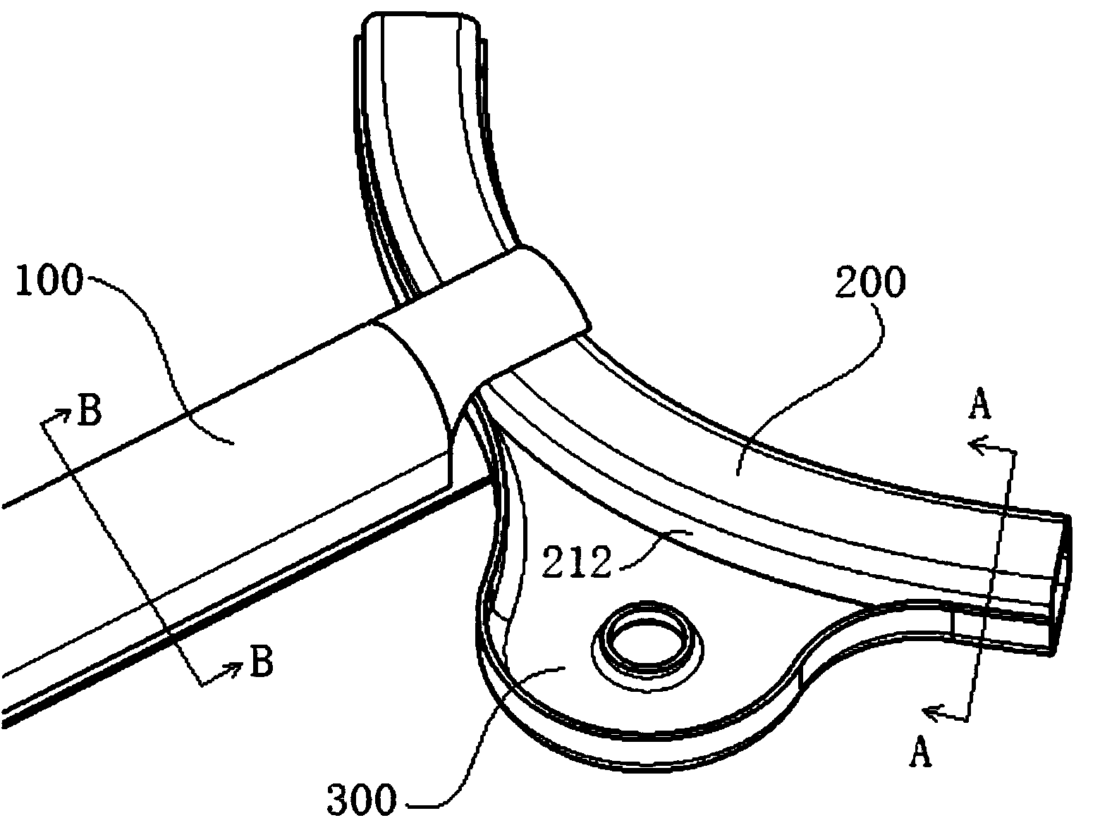
[0036] combine Figure 3 to Figure 6 , In the first embodiment of the present invention, the torsion beam suspension includes a cross beam 100 , a longitudinal arm 200 and a spring tray 300 , and the cross beam 100 is connected to the longitudinal beam 200 . Wherein, the crossbeam 100 includes a crossbeam upper plate 110 and a crossbeam lower plate 120, and the crossbeam upper plate 110 and the crossbeam lower plate 120 are snapped together and welded to form a Image 6 The box-shaped structure shown. There is a notch 111 at the end of the upper beam plate 110, where the longitudinal arm 200 is fully clamped between the upper beam plate 110 and the lower beam plate 120, and then welded, so that, with figure 1 Compared with the structure in which the longitudinal arm 1 and the cross beam 2 are directly overlapped and welded, the force and moment transmitted from the longitudinal arm 200 to the cross beam 100 are uniform, and cracks are less likely to occur. from Figure 4 It...
PUM
 Abstract
Description
Claims
Application Information