
Composite structure of locally applying skin on truss and method for analyzing and calculating safety thereof

A technology of local application and combined structure, applied in the direction of truss structure, special data processing application, truss beam, etc., can solve the problem that the potential bearing characteristics of the skin are not fully utilized, the skin effect is not considered, and the skin effect of the roof panel is weakened. and other problems, to achieve the effect of simple, convenient and accurate calculation, small modeling workload, and reasonable design.

Active Publication Date: 2012-10-17
ARCHITECTURAL DESIGN RES INST OF GUANGDONG PROVINCE +1
View PDF3 Cites 6 Cited by
  • Summary
  • Abstract
  • Description
  • Claims
  • Application Information

AI Technical Summary

Problems solved by technology

However, my country's current construction industry is still in the conceptual stage of skin effect application. Although the domestic construction industry mostly agrees with the advantages and technical effects of skin effect, it has not really applied skin effect to actual projects, especially in the construction of building structures. The skin effect is not considered in the calculation and analysis, and it is only used as a structural safety reserve
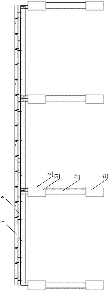
[0006] In the existing calculation and analysis of skin structure applied in the field of architecture, it is generally necessary to calculate and analyze the skin effect from qualitative to quantitative. First, the reliability refers to the reliability of the connection between the roof panel and the purlin, the purlin and the main structure of the building, such as figure 1 As shown, in the existing portal frame system, the roof panel 8 is connected to the purlin 7 and located on the top of the purlin 7, and the purlin 7 is arranged on the main structure 2 of the truss, and the entire roof panel 8 is composed of several overlapping unit panels. The unit plate and the purlins are connected by bolts, and the bolt holes are set on the connection end of the purlins and the main structure of the building. The bolt holes are usually long strip holes, and the bolts are installed in the bolt holes, relying on the bolts and the bolt holes to slide within a certain range , causing a relative displacement between the roof panels and purlins. Although this structure makes the installation of the roof panels and purlins more convenient and can fully release the temperature stress of the roof system, and can reduce the impact of the main structure on the roof panels and purlins, but Weakened the skin effect of the roof panel, did not give full play to the potential bearing characteristics of the skin, and the skin effect may fail, so the skin effect of the roof panel has not been taken as the object of calculation and research; second, the calculation method often uses Simplify the calculation. The simplified calculation only considers the role of the roof panel and does not consider the role of the purlin. This kind of calculation result is distorted and the quantitative effect is poor; however, if the overall model is established according to the actual connection relationship between the purlin and the roof panel, the modeling workload will be large , it is necessary to build all the purlins and roof substructures into the mechanical model to simulate the relationship between the roof, purlins and the main structure. It cannot truly reflect the skin effect and its degree, making it difficult for the skin structure to be practically applied in the field of construction in China

Method used


Image

  • Composite structure of locally applying skin on truss and method for analyzing and calculating safety thereof
  • Composite structure of locally applying skin on truss and method for analyzing and calculating safety thereof
  • Composite structure of locally applying skin on truss and method for analyzing and calculating safety thereof

Examples


Embodiment Construction

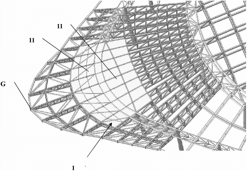
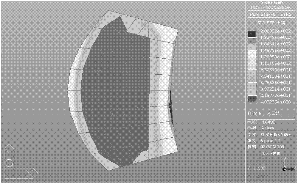
[0068] Such as Figure 1-15 Shown, is the composite structure that a kind of skin of the present invention is partially applied on the truss, comprises truss and purlin, as figure 2 As shown, the truss of this embodiment is a cantilever truss with a length of 23m in the roof steel structure of the gymnasium of the Guangzhou Asian Games in 2010, see Figure 4 , the upper surface of the truss 2 is laid with a skin steel plate 1, the purlin 7 is located above the skin steel plate 1, and the roof panel 8 is arranged on the upper surface of the purlin 7. Specifically, the truss 2 is mainly composed of an upper chord 21 , a web 22 and a lower chord 23 , and the upper surface of the truss 2 refers to the upper flange of the upper chord 21 . After the skin steel plate is set, the stress stiffness of the truss is greatly enhanced, and the bending stiffness of the entire truss is improved, thereby reducing the deflection and stress level of the truss, and it can be used as a reserve f...


PUM


Abstract

The invention discloses a composite structure of locally applying a skin on a truss, comprising a truss and a purline, wherein a skin steel plate is paved on the upper surface of the truss or the lower surface of the truss, and the purline is arranged above the skin steel plate. The invention also discloses a method for analyzing and calculating the safety of the composite structure. According to the invention, the work of modeling is small, the practical operation is simple, the calculation is simple, convenient and accurate, the quantitative analysis of the skin effect can be realized, the bearing behavior of the skin steel plate can be fully presented, the bending resistance, tensile strength and compressive strength of the truss or lower members connected with the skin steel plate are greatly enhanced, the tensile strength and compressive strength of top flanges of the members or top chord of the truss are actually enhanced; and the main structure of buildings can be designed reasonably, thus the technical effects of strengthening structure space stiffness and reducing the consumption of structural steel.

Description

technical field [0001] The invention relates to skin technology in the technical field of architecture, in particular to a composite structure in which skin is partially applied to a truss and an analysis and calculation method for its safety. Background technique [0002] The concept of "skin" comes from the aircraft and ship industry. The skin is often made of metal sheet, which is covered on the longitudinal and transverse ribs to form a ribbed thin shell structure. Because the skin has strong tensile, compressive and shear strength in its own plane, and it works together with the longitudinal and transverse ribs, the stability of the skin structure is very strong. [0003] Skin is used in the field of construction, and most of the skin is covered on the main structure of the building as a roof panel or wall. The skin has a large bearing capacity and rigidity, which can strengthen the overall rigidity of the building. It is very light, and it is also beneficial to reduce...

Claims


Application Information

Patent Timeline
IPC IPC(8): E04C3/08G06F17/50
Inventor 陈星谭坚张卫东区彤陈雄刘雪兵王忠秋关超
Owner ARCHITECTURAL DESIGN RES INST OF GUANGDONG PROVINCE
Learn More