Enhanced thermal management for directed energy weapon

a technology of directed energy and management system, which is applied in the direction of domestic cooling apparatus, lighting and heating apparatus, machines/engines, etc., can solve the problems of inefficient and heavy, large amount of heat, and low efficiency of dews, and achieves the effect of reducing the number of dews, and reducing the efficiency of dews

Inactive Publication Date: 2018-08-16
HAMILTON SUNDSTRAND CORP
View PDF9 Cites 1 Cited by
  • Summary
  • Abstract
  • Description
  • Claims
  • Application Information

AI Technical Summary

Benefits of technology

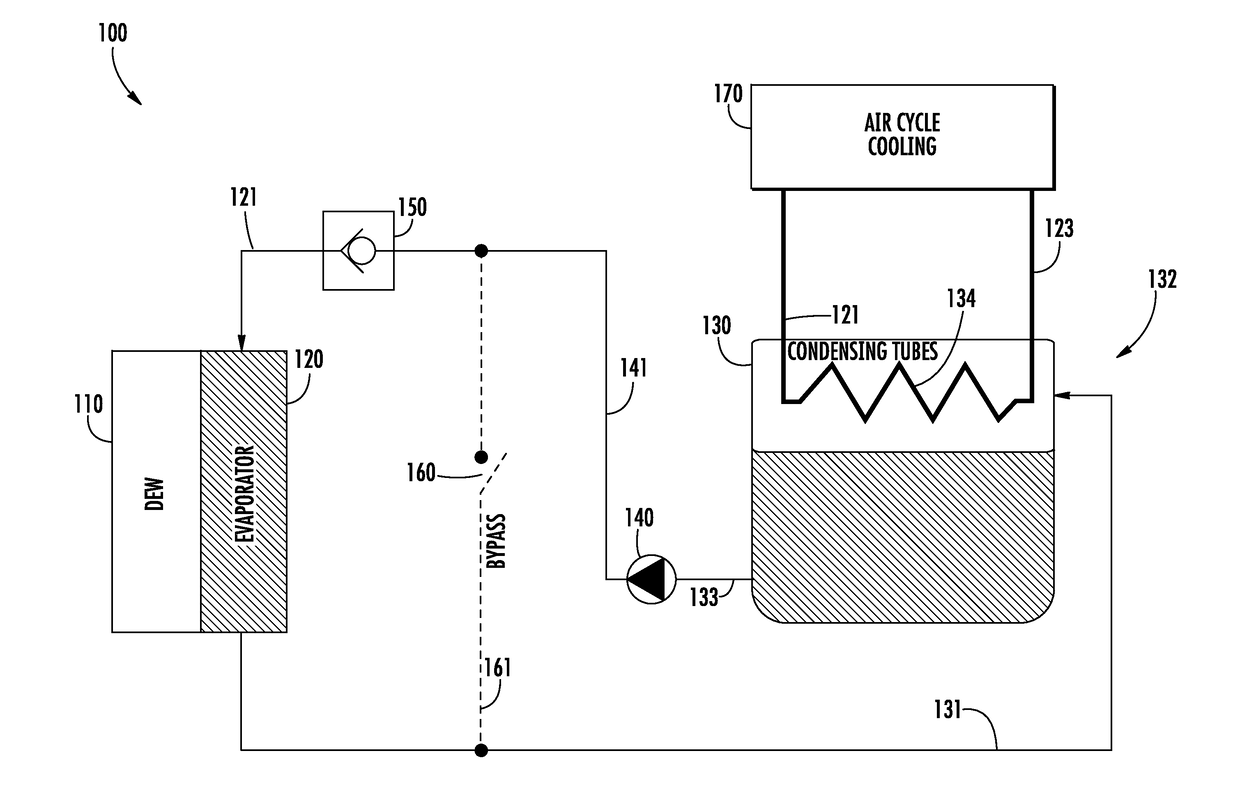
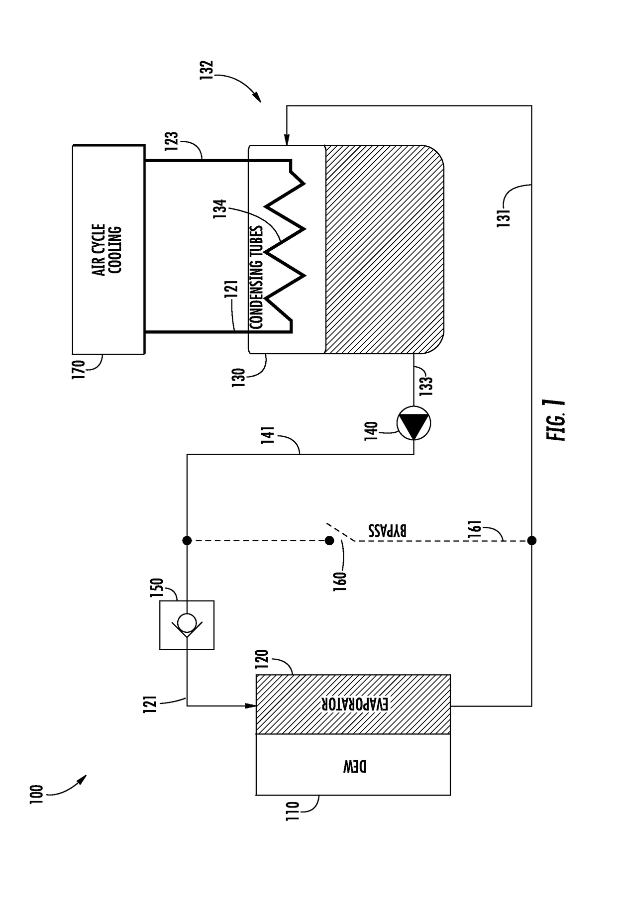
[0026]Technical effects of embodiments of the present disclosure include, but are not limited to a thermal management system and methodology for a directed energy weapon on an aircraft and more specifically, a simplified two phase system for removing heat for a Directed Energy Weapon (DEW).
[0027]The foregoing features and elements may be combined in various combinations without exclusivity, unless expressly indicated otherwise. These features and elements as well as the operation thereof will become more apparent in light of the following description and the accompanying drawings. It should be understood, however, that the following description and drawings are intended to be illustrative and explanatory in nature and non-limiting.

Problems solved by technology

DEWs typically operate at low efficiency and thus, generate a large amount of heat during lasing (weapon firing) operation.
This large thermal transient may drive the size of the thermal management system (TMS) used to control the thermal loading of the DEW Such requirements may result in a TMS that is significantly oversized, in-efficient and heavy for normal operating (non-lasing) modes, particularly for airborne applications.
However, the current proposed solutions either are of very large size & weight or consume coolant requiring regular charging.
1) Conventional refrigeration systems (e.g., Freon compression / expansion systems) that cool the system using electricity as the power source;
2) Refrigerant evaporative approaches; which consume refrigerant after every weapon firing event resulting into limitation of weapon use per flight as well as constant maintenance;
3) “Phase change” approaches, which use solidified Phase Change Materials (PCMs). A PCM material, such as ice, that melts to provide cooling, and other systems in which the PCM is regenerated “offline. Some PCM-cooled DEW systems are very complex, employing multiple fluids in chemical reactions; and
4) Multiple Phase Change Heat Exchanger units that are used sequentially, which effect the discharging of one unit while one or more additional exhausted units are being charged for re-use.
To date, systems employing the foregoing approaches are all relatively heavy and / or do not provide optimal operational flexibility.
The latter drawback is a relatively important one for laser weapons, wherein the major coolant use is for laser diodes, in which water is commonly used as the cooling medium of choice, whereas, the formation of ice requires the use of a material (e.g., a glycol solution) for cooling of the PCM that will remain a liquid below the freezing point of water.

Method used


Image

  • Enhanced thermal management for directed energy weapon
  • Enhanced thermal management for directed energy weapon
  • Enhanced thermal management for directed energy weapon

Examples


Embodiment Construction

[0032]The following description is merely illustrative in nature and is not intended to limit the present disclosure, its application or uses. As used herein, the term controller refers to processing circuitry that may include an application specific integrated circuit (ASIC), an electronic circuit, an electronic processor (shared, dedicated, or group) and memory that executes one or more software or firmware programs, a combinational logic circuit, and / or other suitable interfaces and components that provide the described functionality.

[0033]Additionally, the term “exemplary” is used herein to mean “serving as an example, instance or illustration.” Any embodiment or design described herein as “exemplary” is not necessarily to be construed as preferred or advantageous over other embodiments or designs. The terms “at least one” and “one or more” are understood to include any integer number greater than or equal to one, i.e. one, two, three, four, etc. The terms “a plurality” are unde...


PUM


Abstract

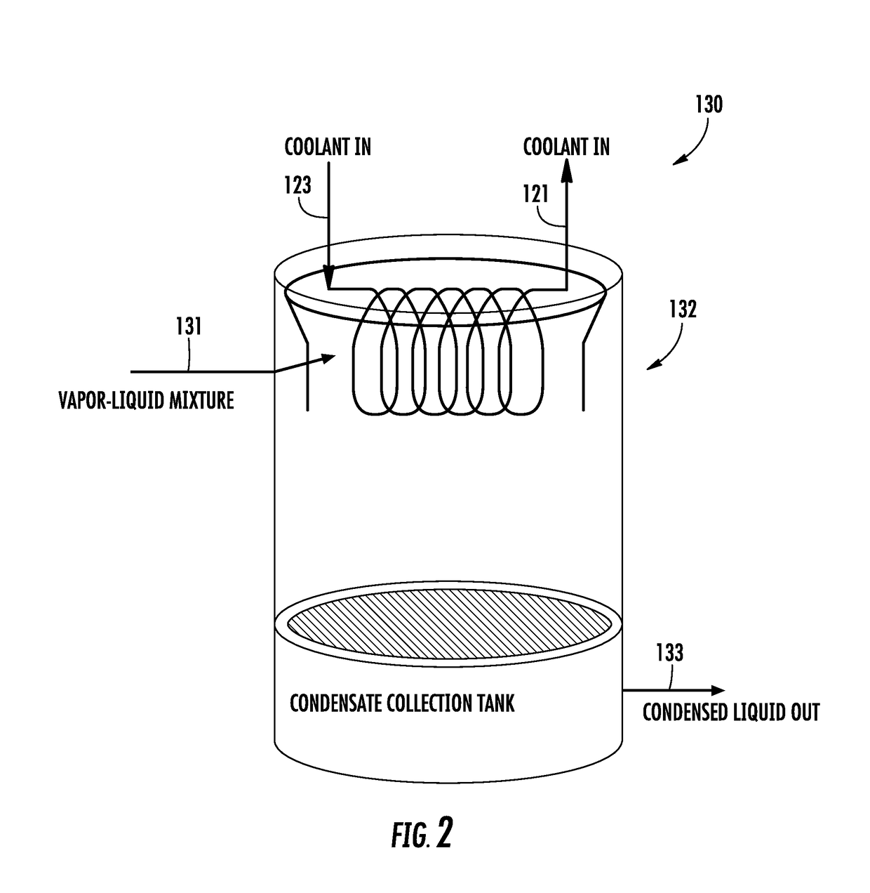
Described herein is a thermal management system and methodology for a directed energy weapon on an aircraft. The thermal management system includes an evaporator in thermal communication with the directed energy weapon and operatively configured to cool the directed energy weapon by evaporating a refrigerant therein. The thermal management system also includes a refrigerant storage tank in fluid communication with the evaporator and a pump in fluid communication with the refrigerant storage tank and the evaporator configured to pump substantially liquid refrigerant to the evaporator.

Description

TECHNICAL FIELD[0001]The subject matter disclosed herein relates to thermal management system for a directed energy weapon and, more specifically, a simplified two phase system for removing heat for a Directed Energy Weapon (DEW).BACKGROUND[0002]Next generation aircraft are being designed with advanced weapons like laser based direct energy weapons (DEWs). DEWs (e.g., laser weapons) may require substantial cooling at the lowest possible weight for sustained operation. DEWs typically operate at low efficiency and thus, generate a large amount of heat during lasing (weapon firing) operation. DEW operation typically consists of relatively brief operating intervals, wherein relatively large “bursts” of cooling are required, interspersed with relatively long intervals in which the weapon is quiescent, and therefore, requires little or no cooling. This large thermal transient may drive the size of the thermal management system (TMS) used to control the thermal loading of the DEW Such requ...

Claims


Application Information

Patent Timeline
Patent Type & Authority Applications(United States)
IPC IPC(8): F41A13/10F41H13/00F25D16/00
CPCF41A13/10F41H13/0043F25D16/00F05D2260/601F41H13/0062
Inventor RANJAN, RAJIVLENTS, CHARLES E.ST. ROCK, BRIAN
Owner HAMILTON SUNDSTRAND CORP
Why Eureka
Try Eureka