Method for producing an anatomical dental implant

a dental implant and anatomical technology, applied in the field of bone replacement and bone replacement, can solve the problems of only possible printing of such a print, significant patient stress, patient treatment errors, etc., and achieve the effect of simplifying treatment, simplifying data use, and simplifying treatment for a medical practitioner

Active Publication Date: 2018-08-23
TRADING COMPANY
View PDF3 Cites 20 Cited by
  • Summary
  • Abstract
  • Description
  • Claims
  • Application Information

AI Technical Summary

Benefits of technology

[0011]A far-reaching automation of the production of a bone replacement is possible by way of the method according to the invention. This can significantly reduce necessary interventions and the time required overall, representing a significant relief for the patient. In particular, the procedure of producing the bone replacement can be automated further, and so the risk of possible human errors is also minimized.
[0046]Preferably, the method further includes a step of ascertaining navigation information, to be precise, in particular, in relation to a mandible or a maxilla. This step may be based, in particular, on the initial data, the processing data, a root canal, a design of a tooth implant, a design of an abutment and / or a design of a dental prosthesis. Such navigation information may be pre-manufactured information for the medical practitioner, simplifying the treatment for the latter such that said medical practitioner immediately knows, for example, the position on the body or on a jaw at which treatment should be effectuated. The navigation information can also be prepared in such a way that it can be immediately processed further in electronic form, for example for an augmented reality system. By way of example, the medical practitioner may use spectacles or a head-up display which facilitates the superposition of such navigation information. This facilitates guiding and informing the medical practitioner during the treatment, without the latter having to interrupt the treatment in order to look up information.

Problems solved by technology

However, this is accompanied by the disadvantage that an intervention has to be undertaken on the patient for this purpose and that, moreover, the formation of such a print is only possible once the cavity is free and accessible from the outside.
On account of the time duration connected therewith, this may constitute a significant stress on the patient.
Moreover, steps to be carried out manually, in particular, produce sources of errors which may lead to errors when treating the patient.

Method used


Image

  • Method for producing an anatomical dental implant
  • Method for producing an anatomical dental implant
  • Method for producing an anatomical dental implant

Examples


Embodiment Construction

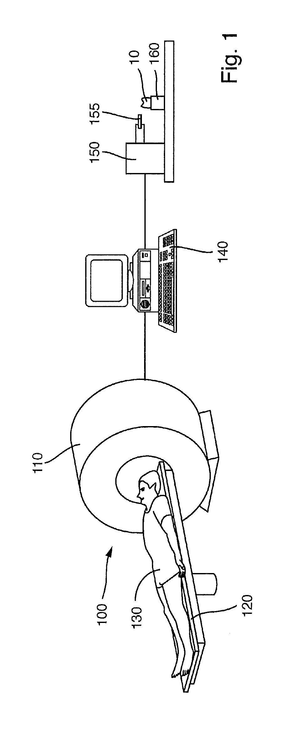
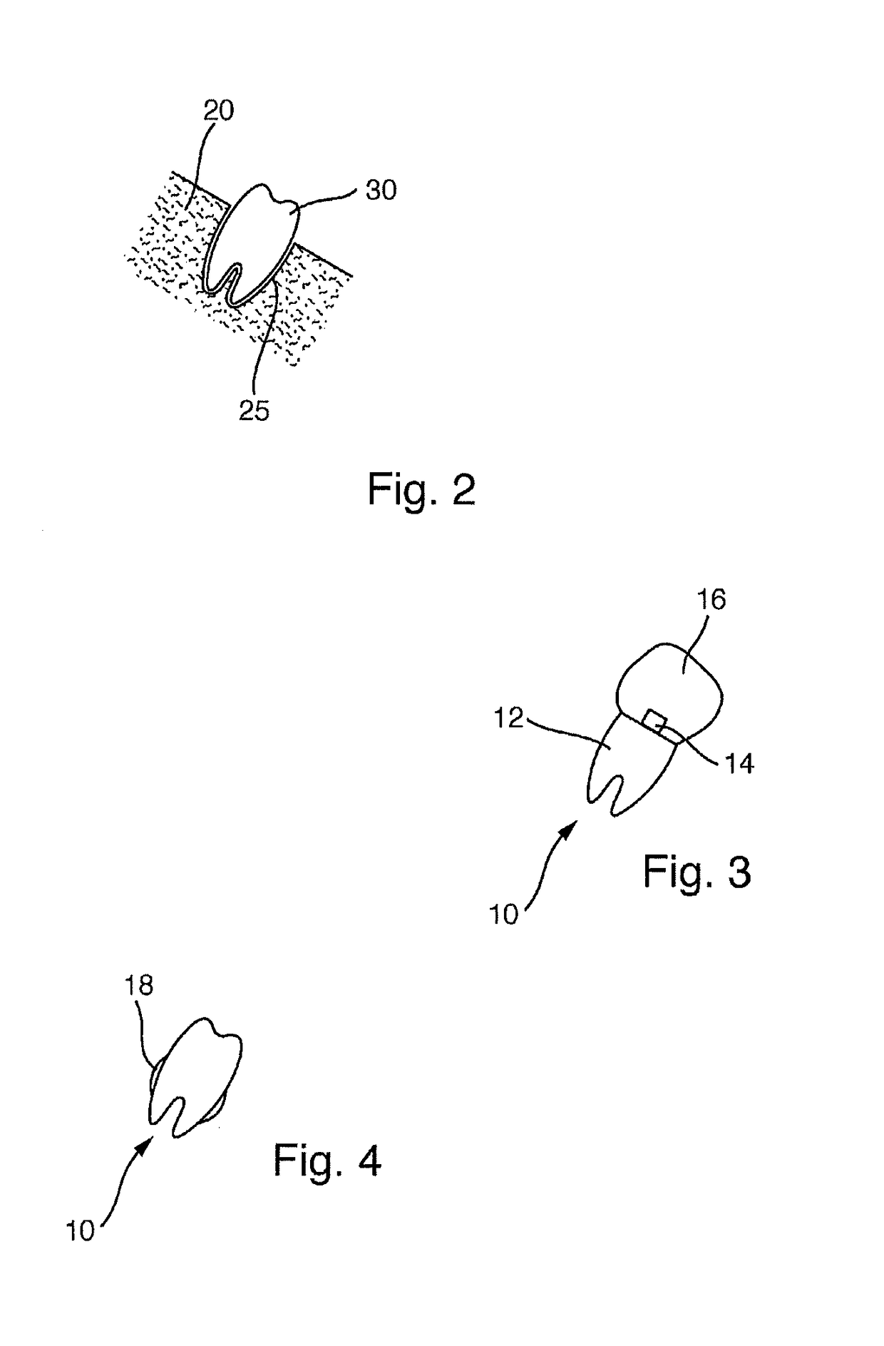
[0055]FIG. 1 shows a system 100 for producing a bone replacement 10.

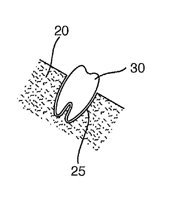
[0056]The system 100 has a computed tomography (CT) scanner 110. A couch 120, on which a patient 130 lies in the present case, is arranged in front of said computed tomography scanner. The couch 120 can be inserted into the computed tomography scanner 110 such that the patient 130 can be examined by means of the computed tomography scanner 110. In particular, this allows the measurement of a cavity in a bone of the patient 130, for which a bone replacement is intended to be produced. In particular, this can be used to measure a cavity for receiving a tooth and also the tooth situated therein.

[0057]The system 100 further comprises a computer 140 which is connected to the computed tomography scanner 110 for the purposes of receiving data. Depending on its measurement of the patient 130, the computed tomography scanner 110 produces initial data which are supplied to the computer 140. Said data may be both indicative fo...


PUM

PropertyMeasurementUnit
computed tomographyaaaaaaaaaa
CTaaaaaaaaaa
magnetic resonance imagingaaaaaaaaaa

Abstract

A method for producing a bone replacement, a cavity or a bone being detected in a fully automated manner and the bone replacement being produced based on the detection also in a fully automated manner. It is also possible to produce information in relation to medical instruments or navigation information in a fully automated manner.

Description

BACKGROUND AND PRIOR ART[0001]The invention relates to a method for producing a bone replacement and to a bone replacement.[0002]Bone replacements can be inserted into human or animal bones in order to replace a piece of bone that is no longer present or should be removed. By way of example, such a replacement may become necessary if a tooth root, on account of disease, is destroyed, not disposed or otherwise defective, or if part of a bone was knocked out on account of an accident.[0003]As a rule, it is necessary, for bone replacements, to establish a fit that is as good as possible between a bone replacement and a cavity in which the bone replacement should be received. This facilitates a fit without play and a good seat in the long-term.[0004]Known methods for producing a bone replacement are typically based on taking a print of the cavity using a mass which can solidify in the cavity and producing the bone replacement on the basis thereof. However, this is accompanied by the dis...

Claims


Application Information

Patent Timeline
Patent Type & Authority Applications(United States)
IPC IPC(8): A61C13/00A61C8/00A61B6/03
CPCA61C13/0004A61C13/0019A61C8/0036A61B6/032A61B6/14A61F2002/2835A61F2/2803B33Y80/00A61F2002/2889B33Y10/00A61C13/0013
Inventor JAHN, DIRK
Owner TRADING COMPANY
Why Eureka
Try Eureka