Knob structure and follow focus remote controller using same

Active Publication Date: 2018-08-23
SZ DJI OSMO TECH CO LTD
View PDF0 Cites 2 Cited by
  • Summary
  • Abstract
  • Description
  • Claims
  • Application Information

AI Technical Summary

Benefits of technology

[0022]In some embodiments, the mating wheel can include a ring structure having through-holes for accommodating the plurality of damping blocks.

Problems solved by technology

However, a limited volume of the damping grease can be provided as a contact area between the rotational assembly and the fixed member is small.
A leakage of the damping grease from a space between the rotational assembly and the fixed member may happen if the pressure applied on the damping grease from the rotational assembly and the fixed member is increased.
In such cases, a

Method used


Image

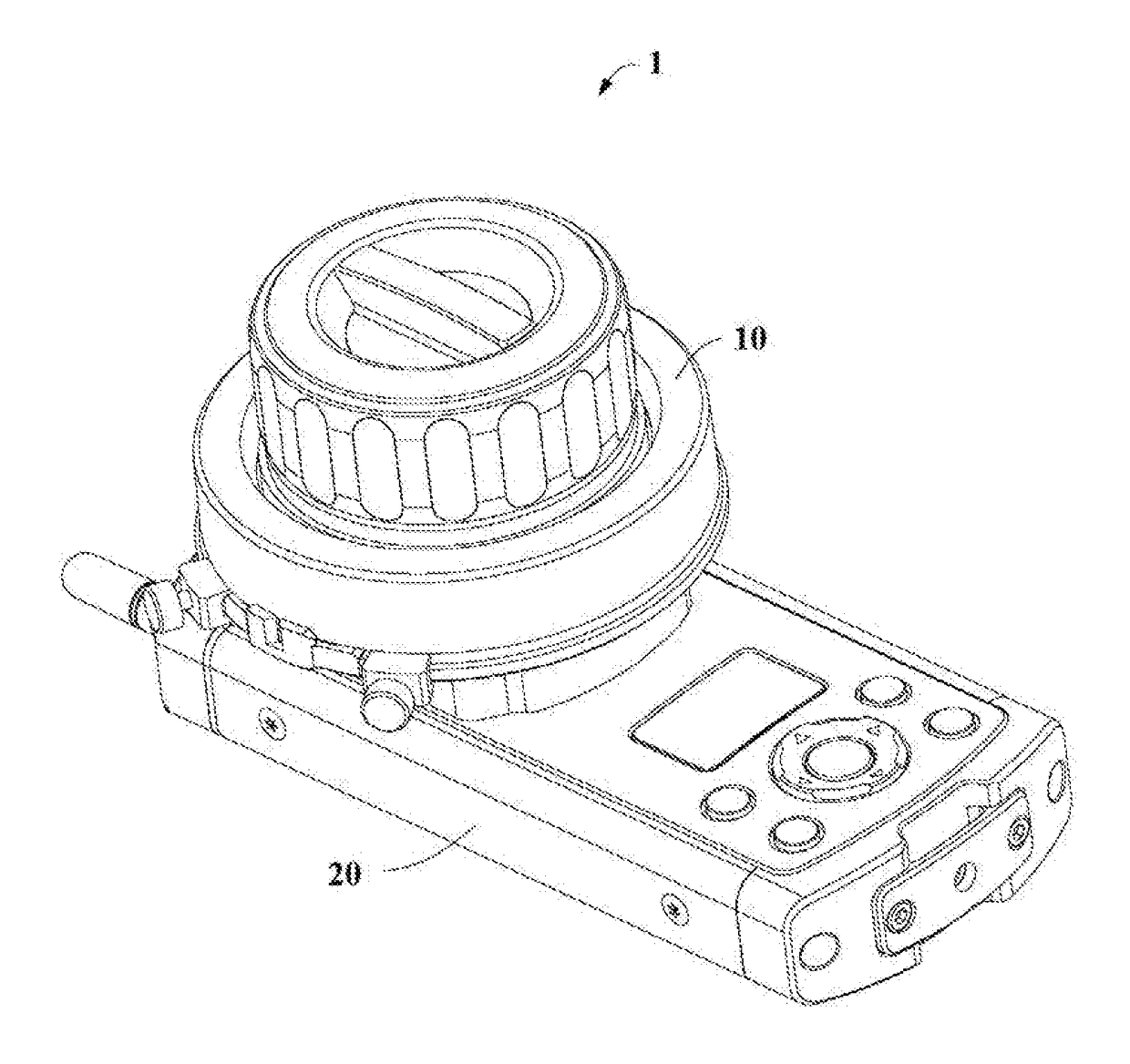
  • Knob structure and follow focus remote controller using same
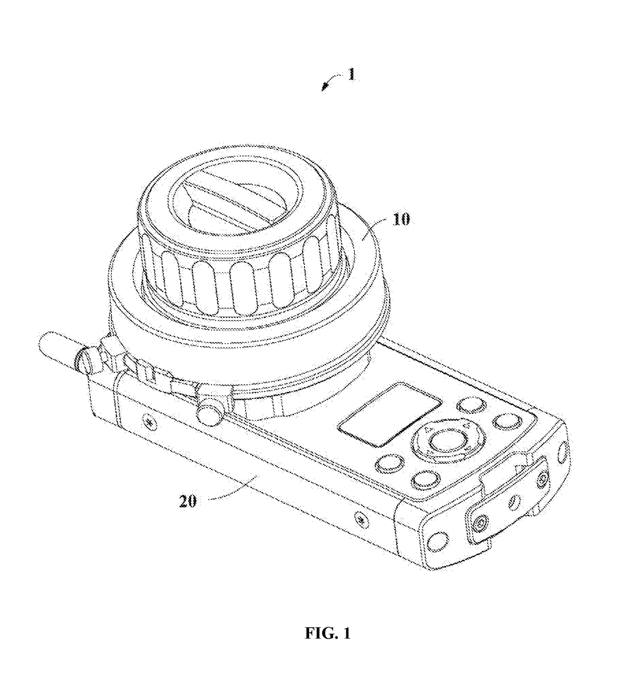
  • Knob structure and follow focus remote controller using same
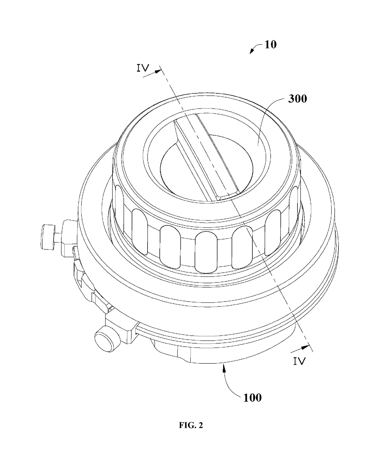
  • Knob structure and follow focus remote controller using same

Examples


Example

LIST OF REFERENCE NUMERALS

[0040]

TABLE 1Follow-focus remote controller1, 3Body20, 32Knob structure10, 30Fixed assembly100Bearing101Bearing through hole1011Fixed member102Bearing portion1021Carrying platform1022Penetration hole1023Central shaft103Mating portion1030Snapping portion1032Connecting portion1033Fixed portion1034Sheathing portion1035Rotational assembly300Operating member301Adjusting wheel302Snapping portion3020Hand wheel304Mounting hole3040, 3060Mating wheel306Central disk3062Through-hole3064, 5042Spoke3066Accommodation hole3068Adjusting assembly500First elastic member501Pressure knob502Sleeve portion5020Guiding portion5022Step5024Retaining member504Mounting portion5040Stopper5044Second elastic member506Pressure plate508Pressure plate through-hole5080First disk5082Second disk5084Damping plate70Damping block700Dangling member34Holding hole320Inner wall322Groove324Hanging ring340Casing342Movable member344Insertion portion3420Operating portion3422Protrusion3424Slider3426Plug342...


PUM


Abstract

A knob structure includes a fixed member, a rotational assembly, and a damping element. The fixed member includes a carrying platform. The rotational assembly is rotatably disposed on the fixed member. The damping element is disposed between the carrying platform and the rotational assembly. A contact area between the carrying platform and the damping element is configured to be changed by a rotation of the rotational assembly.

Description

[0001]This application is a continuous application of International Application No. PCT / CN2015 / 092340, filed on Oct. 20, 2015, the entire contents of which are incorporated herein by reference.TECHNICAL FIELDTechnical Field[0002]The present disclosure relates to a knob structure, and more particularly to a knob structure for controlling an imaging device and a follow-focus remote controller having the knob structure.Background of the Disclosure[0003]Conventional follow-focus remote controllers can control a focusing of an imaging device with a knob structure. The knob structure can comprise a fixed member, a rotational assembly rotatable relative to the fixed member and a damping grease provided between the rotational assembly and the fixed member. The rotational assembly can be made of an elastic material such as plastic or rubber, while the fixed member can be made of metal. A rotational resistance between the rotational assembly and the fixed member can be adjusted by changing a ...

Claims


Application Information

Patent Timeline
IPC IPC(8): G05G1/12H04N5/232
CPCG05G1/12H04N5/232G03B3/12G05G1/08G05G5/03H04N23/60
Inventor LIU, GUOYAOZHAO, YANCHONGLI, WEIDONGPAN, PAUL
Owner SZ DJI OSMO TECH CO LTD
Why Eureka
Try Eureka