Remote perception of depth and shape of objects and surfaces

a technology of depth and shape, applied in the field of remote perception of objects and surfaces, can solve the problems of inability to intuitively navigate using visual perception, inability to provide visual information in many circumstances, and inability to use intuitive navigation methods

Active Publication Date: 2018-08-23
MAHERIYA KIRAN K
View PDF14 Cites 9 Cited by
  • Summary
  • Abstract
  • Description
  • Claims
  • Application Information

AI Technical Summary

Benefits of technology

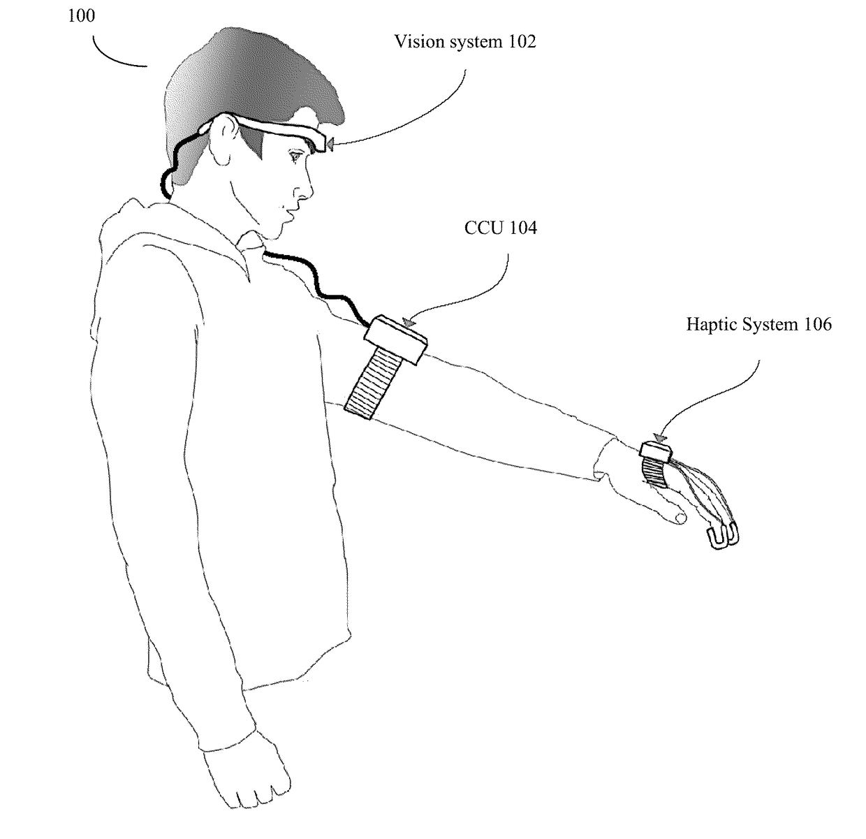
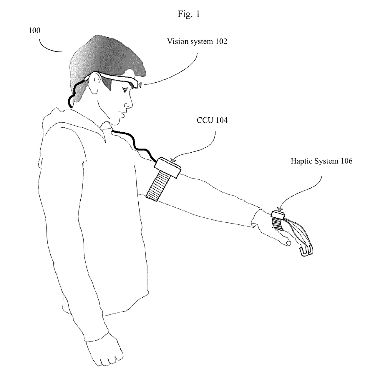
[0020]Once the user has perceived the object (the open door in this example), they can decide to approach the object by walking in the direction of it or scan for other objects, and repeat the process intuitively. The remote shape perception provided by the device is continuous and dynamic to enable the user to move around freely in real world—indoors or outdoors—and interact with objects without requiring touch.

Problems solved by technology

This intuitive navigation method using visual perception is, unfortunately, not available to the visually impaired.
Similarly, such visual information is also not available in many circumstances that rescue workers, e.g., firefighters, encounter.

Method used


Image

  • Remote perception of depth and shape of objects and surfaces
  • Remote perception of depth and shape of objects and surfaces
  • Remote perception of depth and shape of objects and surfaces

Examples


Embodiment Construction

[0037]Definitions:

[0038]Virtual pointer: direction of user interest as determined by various pointing sensors. Image patch: A narrow angle patch or surface in both the horizontal and vertical directions, with dimensions between about 1 degree to about 10 degrees in the horizontal and vertical, which surrounds the virtual pointer, and is somewhat analogous to the region of sharp vision in the human eye. Pointing direction: the image patch or surface designated by a particular pointing vector. As the image patch (surface) shrinks in size, the pointing direction tends to approximate the virtual pointer, and thus the terms are sometimes used interchangeably when the context is clear. Pointing region (also known as the field of view or FOV). A wider angle “patch” or “surface” typically surrounding both the virtual pointer and the pointing direction and the narrower “image patch”. The field of view will often have dimensions between about 45 degrees to 180 degrees in both the horizontal a...


PUM


Abstract

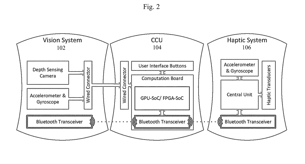
A computer implemented method of mobile visual assistance to allow users to rapidly distinguish distances to and shapes of multiple objects. 3D images of the environment are obtained using a plurality of user worn video sensors, such as head mounted video cameras. The users are often equipped with a glove like device comprising pointing direction sensors and various haptic transducers. As the user moves though the environment, computer processors use the video sensors to detect various objects in front of the user and report these using secondary or coarse level haptic transducers. The user can use the glove-like device to point at various objects of specific interest, and the system can report further information such as shape or texture data using primary haptic transducers, allowing the user the haptic version of a sharper narrow field of view superimposed on a haptic version of a wider peripheral field of view.

Description

CROSS REFERENCE TO RELATED APPLICATIONS[0001]This application claims the priority benefit of U.S. provisional patent application 62 / 471,293, filed Mar. 14, 2017; this application is also a continuation in part of U.S. patent application Ser. No. 15 / 728,379, filed Oct. 9, 2017; application Ser. No. 15 / 728,379 was a continuation in part of U.S. patent application Ser. No. 15 / 411,837, filed Jan. 20, 2017, now U.S. Pat. No. 9,792,501; application Ser. No. 15 / 728,379 also claimed the priority benefit of U.S. provisional patent application 62 / 441,284, filed Dec. 31, 2016; the complete contents of all of these applications are included herein by reference.BACKGROUND OF THE INVENTIONField of the Invention[0002]This invention is in the field of computerized visual assistance devices for the visually impairedDescription of the Related Art[0003]According to a WHO 2010 global survey, the number of people who are visually impaired is “estimated to be 285 million, of whom 39 million are blind”. P...

Claims


Application Information

Patent Timeline
Patent Type & Authority Applications(United States)
IPC IPC(8): G06F3/01G06T7/593G06F3/0346
CPCG06F3/014G06F3/016G06T7/593G06F3/012G06F3/0346G06F2203/0331
Inventor MAHERIYA, KIRAN K.
Owner MAHERIYA KIRAN K
Why Eureka
Try Eureka