Video-assisted laryngeal mask airway devices

a technology of laryngeal mask and airway device, which is applied in the field of laryngeal mask airway device, can solve the problems of not protecting against the risks of regurgitation and aspiration, inability to intubate the trachea, and possible gastric acid soiling of the lungs

Inactive Publication Date: 2006-07-27
EZC HLDG
View PDF6 Cites 54 Cited by
  • Summary
  • Abstract
  • Description
  • Claims
  • Application Information

AI Technical Summary

Benefits of technology

[0019] It is also an object of this invention to provide to provide single-use LMA devices that incorporate low-cost, solid state camera components, such as a CCD, CMOS or NMOS video sensor and an illumination source, such as a light emitting diode (“LED”), that may be coupled to a reusable processing unit and display screen.
[0020] It is another object of the present invention to provide LMA devices having two or more video sensors with intersecting fields of view, thereby enabling the clinician to obtain a stereoscopic view of the patient's airway.
[0021] It is a further object of this invention to provide LMA devices wherein the inflatable cuff is arranged to be self-expanding, thereby obviating the need for the clinician to separately attend to inflating the cuff during placement of the LMA device.
[0022] These and other objects of the present invention are accomplished by providing a LMA device, configured as either an LMA or ILM, that incorporates a video sensor, such as a CCD, CMOS or NMOS sensor, arranged to provide an image of the laryngeal inlet and / or other airway structures. In this manner, the LMA device of the present invention permits the clinician to have immediate optical confirmation of the position of the mask aperture relative to the laryngeal inlet from the moment of insertion of the device and at any time thereafter. In the case of an intubating laryngeal mask, the video sensor permits image-guided intubation using a conventional endotracheal tube. In one preferred embodiment, the LMA device may include two or more video sensors having intersecting fields of view, thereby providing a stereoscopic view of the patient's airway.

Problems solved by technology

LMAs permit ventilation of the patient without placing an endotracheal tube into the trachea, but do not protect against the risks of regurgitation and aspiration.
However, intubation of the trachea is not always possible and, when difficulty is experienced, soiling of the lungs with gastric acid may occur while attempts are being made to intubate.
ILMs have the limitation that, for a high degree of success in passing an endotracheal tube through the ILM tube into the trachea, fiberscopic aid is needed to ensure the endotracheal tube does not pass into the esophagus or collide with and injure the epiglottis.
These hazards, particularly the former, which may result in death if undetected, are similar to those encountered in classical intubation using a laryngoscope.
However, fiberoptic assisted intubation has the disadvantage that it requires considerable skill and time, significant drawbacks in cases where brain damage or death from lack of oxygen are imminent if ventilation cannot be achieved.
Insertion of the fiberscope in this manner takes time and skill.
In addition, the tip of the fiberscope is not protected from contamination with secretions present in the pharynx or from bleeding provoked by its passage, either or both of which may obscure the fiberscope operator's view.
Moreover, a further problem encountered with fiberoptic assisted intubation is that the view is two-dimensional and the field of vision is very restricted.
The combination of all these factors makes fiberoptic assisted intubation a difficult skill to acquire and maintain.
Lastly, fiberscopes are very expensive and not all hospitals are able to afford or maintain them, thereby adding to the difficulty of ensuring that clinicians have the necessary skill to use the technique.
However, a fiberscope still has to be inserted in the tube to ascertain whether accurate alignment has been achieved.
Although the foregoing patents to Brain disclose LMA devices that include fiberoptic components to enhance viewing, there are several disadvantages to the use of optical fibers.
Generally, such fibers are susceptible to breakage during bending, require a high degree of illumination, and are susceptible to image distortion as the reflected light travels through the optical fiber.
In addition, the electronics components required to process and display an image transmitted through an optical fiber are expensive, thereby limiting acceptance of such devices.
However, all of these devices suffer from the disadvantage noted above.
Specifically, none of these devices provide an adequate degree of ventilation to the patient while the intubation process is underway.

Method used


Image

  • Video-assisted laryngeal mask airway devices
  • Video-assisted laryngeal mask airway devices
  • Video-assisted laryngeal mask airway devices

Examples


Embodiment Construction

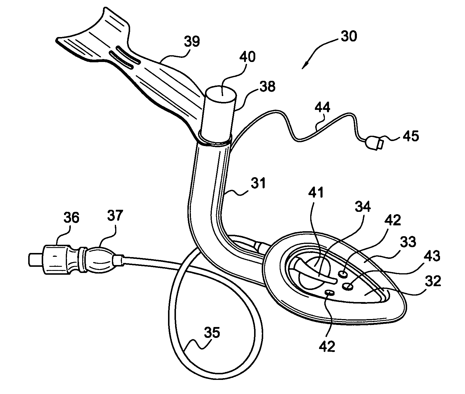
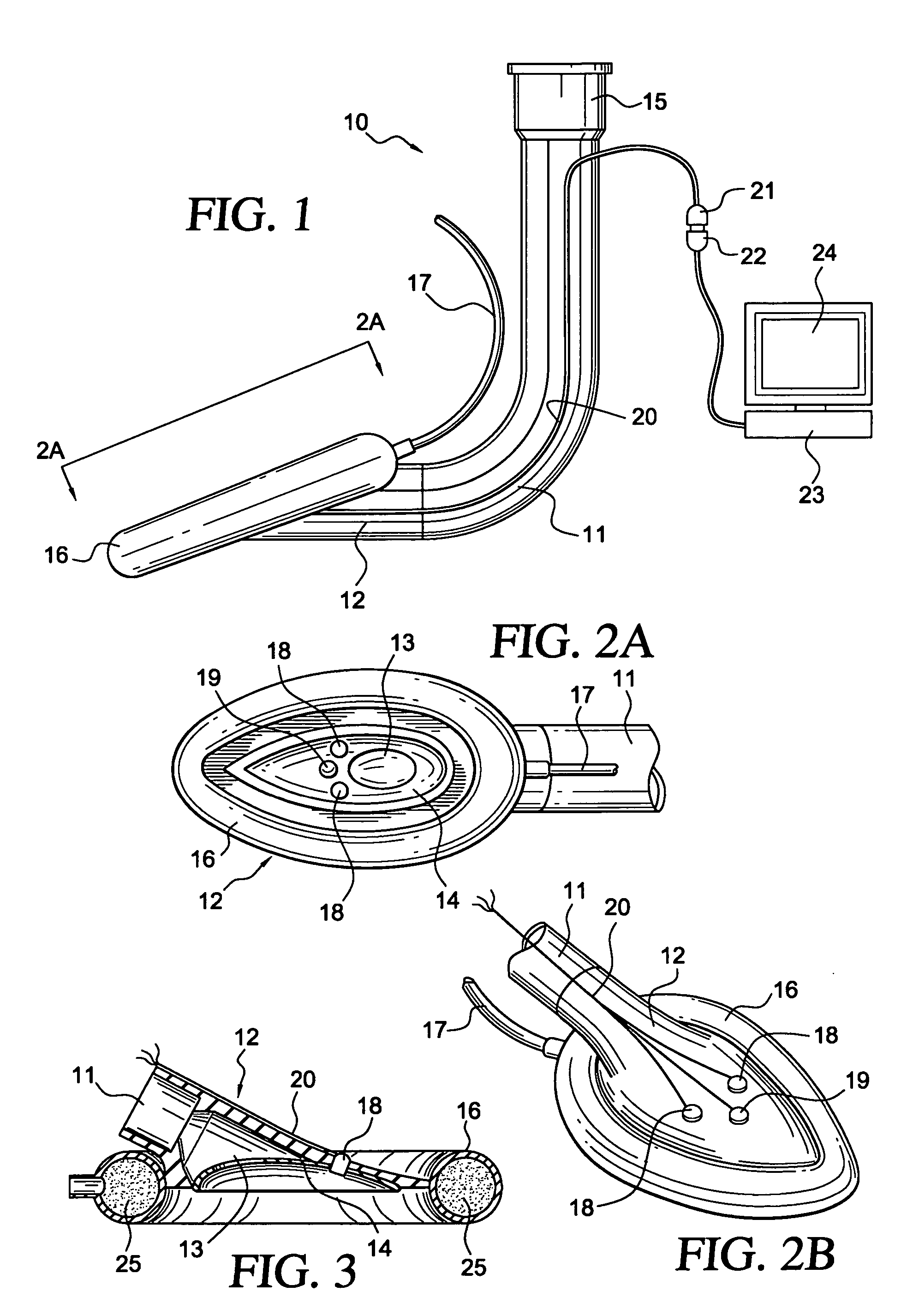
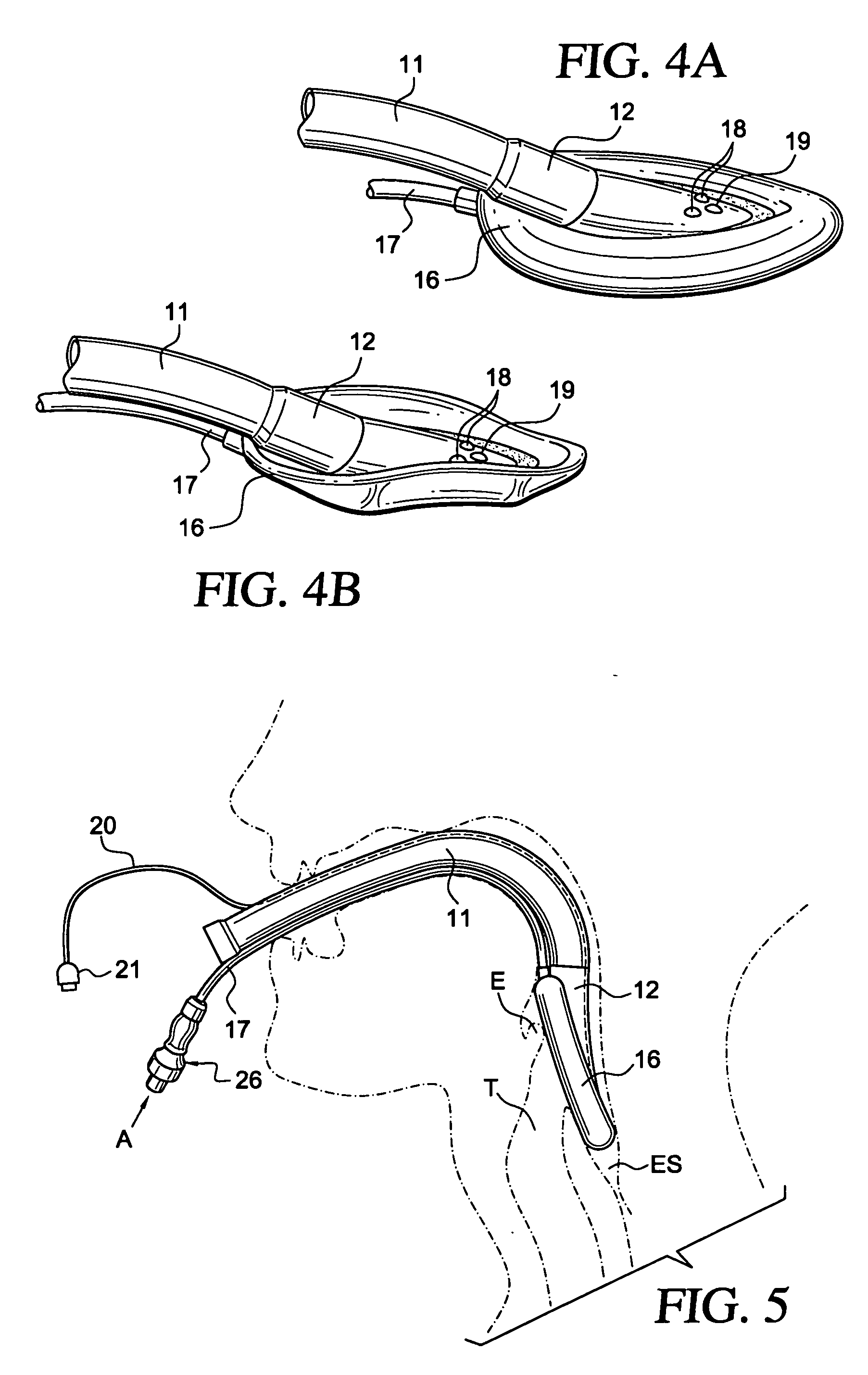
[0033] In accordance with the principles of the present invention, a video laryngeal mask airway (“LMA”) device is provided to facilitate lung ventilation in an unconscious patient, comprising an airway tube and a mask attached to an end of the airway tube. The mask communicates with the airway tube and includes a peripheral cuff having a roughly elliptical shape that is configured to conform to and readily fit within the space behind the larynx. In this manner, the cuff forms a seal around the circumference of the laryngeal inlet without the device penetrating into the interior of the larynx. In accordance with the present invention, the mask carries at least one video sensor having a field of view that encompasses the laryngeal inlet when the mask is inserted into the patient's airway. The LMA device, which may be configured as either an LMA or ILM, preferably is disposed of after a single use. Alternatively, the LMA device may have the video sensors oriented within the mask porti...


PUM


Abstract

A laryngeal mask airway device is provided that incorporates a video sensor, such as a CCD, CMOS or NMOS imaging chip, arranged to provide an image of the laryngeal inlet or other airway structures. The video sensor is electrically coupled to a reusable processing unit that receives the signals generated by the video sensor and generates a digital image of the interior of the patient's airway, thereby enabling the clinician to have immediate optical confirmation of the position of the mask aperture relative to the laryngeal inlet from the moment of insertion of the device.

Description

FIELD OF THE INVENTION [0001] The present invention relates to laryngeal mask airway devices, such as laryngeal mask airways and intubating laryngeal masks, for use in administering anesthesia having one or more video sensors mounted in the bowl of the device to assist in placement of the device or insertion of an endotracheal tube. BACKGROUND OF THE INVENTION [0002] Laryngeal mask airways (“LMA”) are known for use in administering anesthesia in lieu of, or in conjunction with endotracheal tubes. LMAs permit ventilation of the patient without placing an endotracheal tube into the trachea, but do not protect against the risks of regurgitation and aspiration. Commercially available LMAs are designed to reduce the risk encountered with endotracheal tubes of improper placement of the tube in the esophagus rather than then trachea, and are now are used in more than ⅓ of all anesthetic procedures. Such devices generally include a flexible tube that is coupled to and communicates with a ma...

Claims


Application Information

Patent Timeline
Patent Type & Authority Applications(United States)
IPC IPC(8): A62B9/06A61M16/00
CPCA61B1/06A61B1/267A61M16/04A61M16/0488A61M16/0409A61M16/0445A61M16/0436
Inventor GLASSENBERG, RAYMONDKIMMEL, ZEBADIAH
Owner EZC HLDG
Why Eureka
Try Eureka