Systems and Methods for Remote Tagging and Tracking of Objects Using Hyperspectral Video Sensors

a video sensor and hyperspectral technology, applied in image analysis, image enhancement, instruments, etc., can solve the problems of difficult association, difficult detection and discrimination of unambiguous objects and background, and difficult detection of objects in images, so as to reduce false alarms, high spatial and temporal resolution, and high spectral resolution

Active Publication Date: 2010-12-23
THE JOHN HOPKINS UNIV SCHOOL OF MEDICINE
View PDF19 Cites 55 Cited by
  • Summary
  • Abstract
  • Description
  • Claims
  • Application Information

AI Technical Summary

Benefits of technology

[0017]The performance of many existing tracking algorithms suffers when there are multiple objects with similar appearance/color in the sensor's FOV. The invention described herein addresses this problem by exploiting high-resolution reflectance spectra, which often provides a unique signature/fingerprint that can distinguish the tracked object from others with the same color. For example, when tracking a single white object of interest in a crowd of white objects, the reflectance spectrum of the object of interest can be used to discriminate it from the other white objects, and thus reduce the false alarms that often confuse existing surveillance systems.
[0018]A hyperspectral video surveillance system is described herein, which uses a hyperspectral video (HSV) camera. This sensor captures hyperspectral imagery at near-video rates. While standard video cameras capture only three wide-bandwidth color images, the HSV camera collects many narrow-bandwidth images of the scene. For many vision systems, an HSV camera provides several advantages. An HSV c

Problems solved by technology

Detecting objects in images is often difficult when objects in the scene have similar appearance (e.g., shape and intensity).
However if this object's specific spectral signature is known, it can then be unambiguously detected a

Method used


Image

  • Systems and Methods for Remote Tagging and Tracking of Objects Using Hyperspectral Video Sensors
  • Systems and Methods for Remote Tagging and Tracking of Objects Using Hyperspectral Video Sensors
  • Systems and Methods for Remote Tagging and Tracking of Objects Using Hyperspectral Video Sensors

Examples


Embodiment Construction

[0027]A preferred embodiment of the present invention is now described with reference to the figures, where like reference numbers indicate identical or functionally similar elements. Also in the figures, the leftmost digit of each reference number corresponds to the figure in which the reference number is first used. While specific configurations and arrangements are discussed, it should be understood that this is done for illustrative purposes only. A person skilled in the relevant art will recognize that other configurations and arrangements can be used without departing from the spirit and scope of the invention. It will be apparent to a person skilled in the relevant art that this invention can also be employed in a variety of other systems and applications.

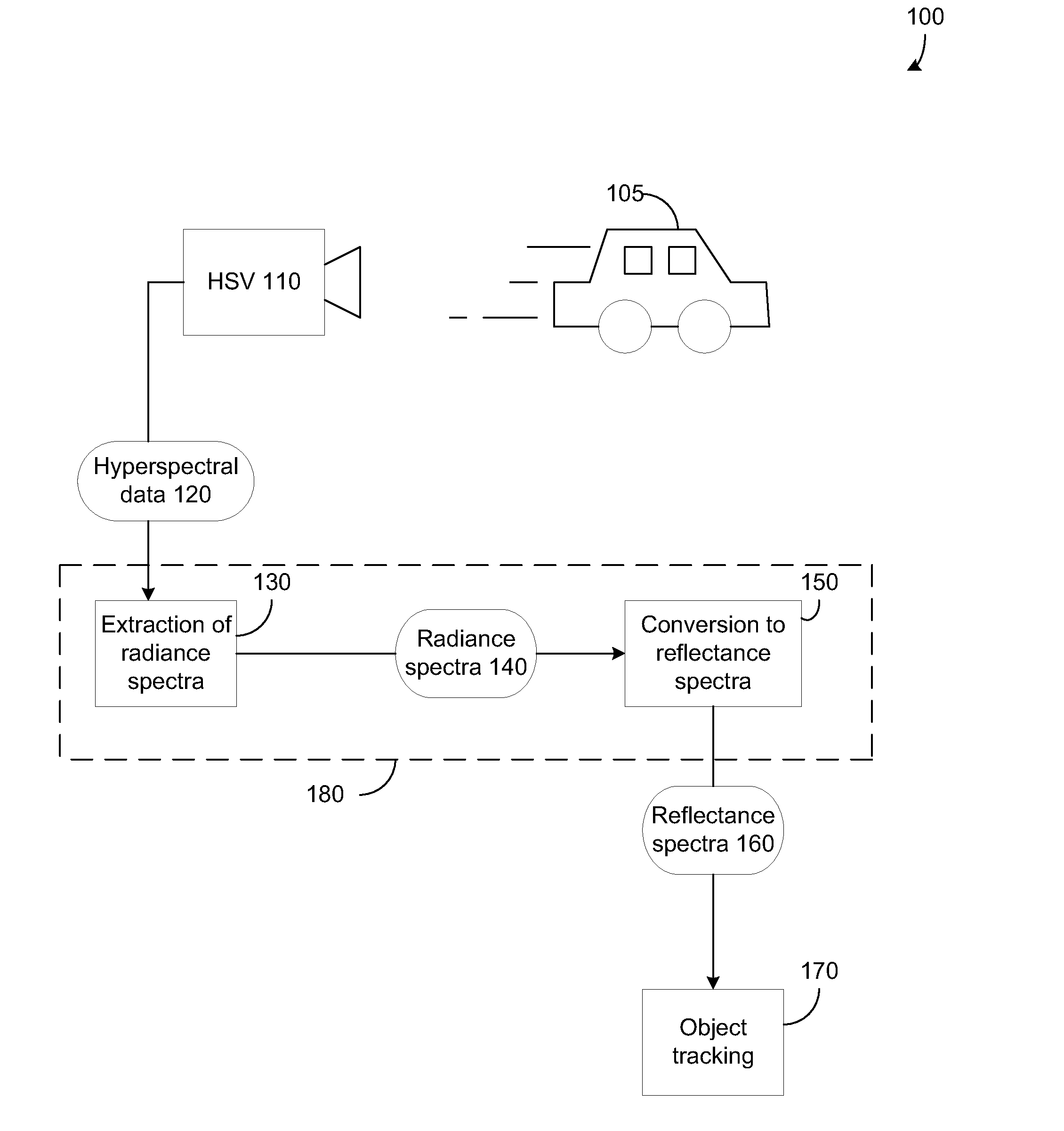
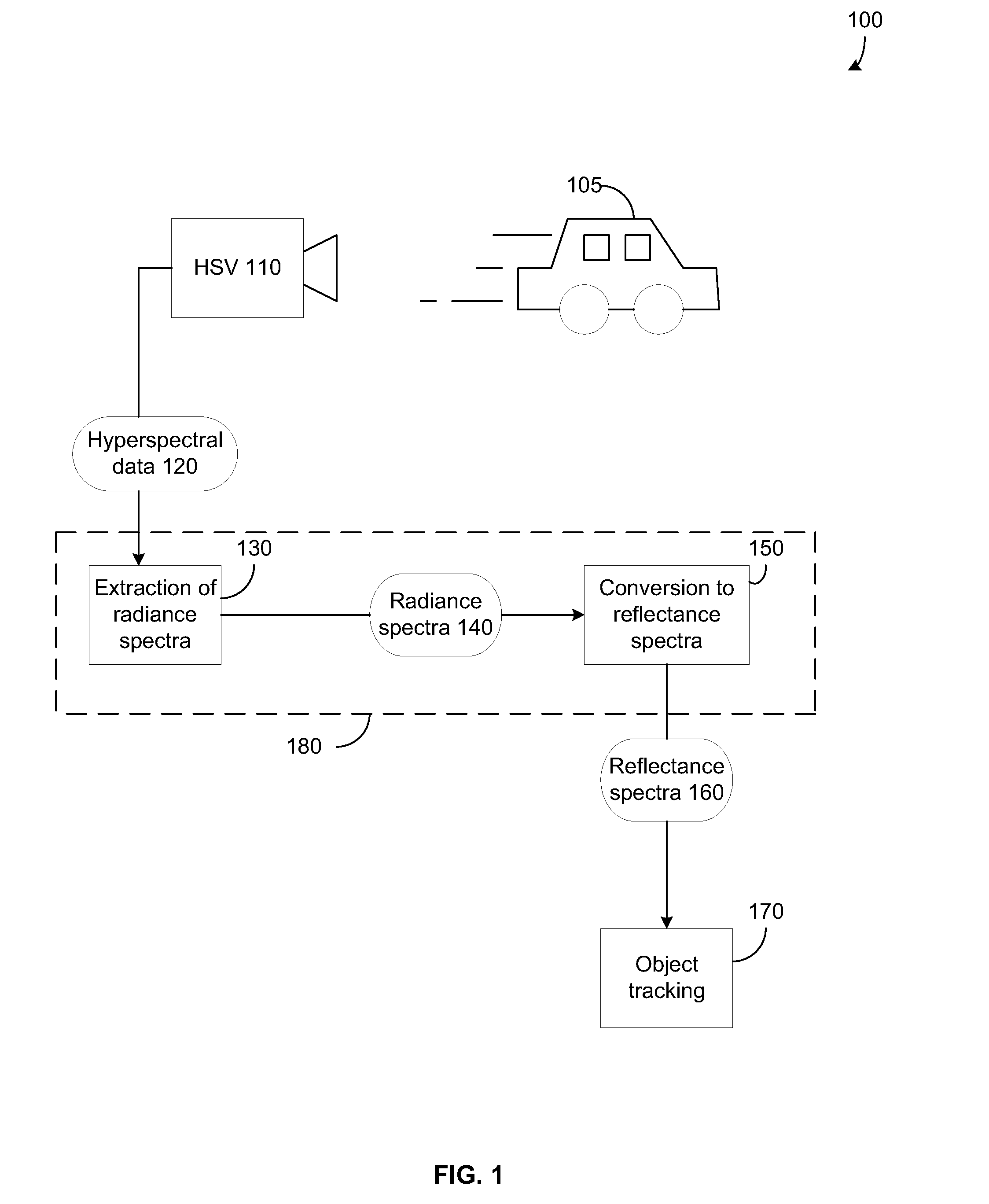
[0028]FIG. 1 illustrates the overall system of the invention, according to an embodiment. An object 105 is shown being imaged by a hyperspectral video (HSV) camera 110. Most modern video cameras provide imagery with high spa...


PUM


Abstract

Detection and tracking of an object by exploiting its unique reflectance signature. This is done by examining every image pixel and computing how closely that pixel's spectrum matches a known object spectral signature. The measured radiance spectra of the object can be used to estimate its intrinsic reflectance properties that are invariant to a wide range of illumination effects. This is achieved by incorporating radiative transfer theory to compute the mapping between the observed radiance spectra to the object's reflectance spectra. The consistency of the reflectance spectra allows for object tracking through spatial and temporal gaps in coverage. Tracking an object then uses a prediction process followed by a correction process.

Description

CROSS REFERENCE TO RELATED APPLICATION[0001]This application claims the benefit of U.S. Provisional Application No. 61 / 269,317, filed on Jun. 22, 2009 which is incorporated herein by reference in its entirety.BACKGROUND OF THE INVENTION[0002]1. Field of the Invention[0003]The invention described herein relates to imaging and object tracking.[0004]2. Background Art[0005]Acquiring and tracking a moving object can be aided by automated processing to improve speed and accuracy. Such processing may include technology that includes computer vision. Computer vision algorithms generally exploit shape and / or appearance features for automated analysis of images and video.[0006]Appearance-based methods are challenged by the changes in an object's appearance. The changes may be due to several factors. These may include a) different illumination sources and conditions, b) variations of the object's orientation with respect to the illumination source and camera, and c) different reflectance prope...

Claims


Application Information

Patent Timeline
IPC IPC(8): G06K9/00G06V10/143G06V10/60
CPCG06K9/2018G06K9/4661G06T2207/20081G06T7/208G06T2207/10036G06T7/2033G06T7/246G06T7/277G06V10/143G06V10/60
Inventor BANERJEE, AMITBURLINA, PHILLIPPE M.BROADWATER, JOSHUA B.
Owner THE JOHN HOPKINS UNIV SCHOOL OF MEDICINE
Why Eureka
Try Eureka