
Robot with vision-based 3D shape recognition

a 3d shape and robot technology, applied in the field of robots with vision-based 3d shape recognition, can solve the problems of no publications on the topic, no guarantee that such an approach would work, and the inability to reconstruct 3d shape from a single 2d imag

Inactive Publication Date: 2010-11-11
HONDA RES INST EUROPE
View PDF14 Cites 55 Cited by
  • Summary
  • Abstract
  • Description
  • Claims
  • Application Information

AI Technical Summary

Benefits of technology

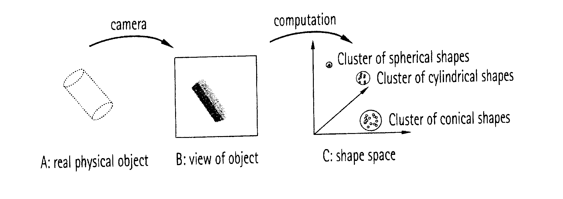
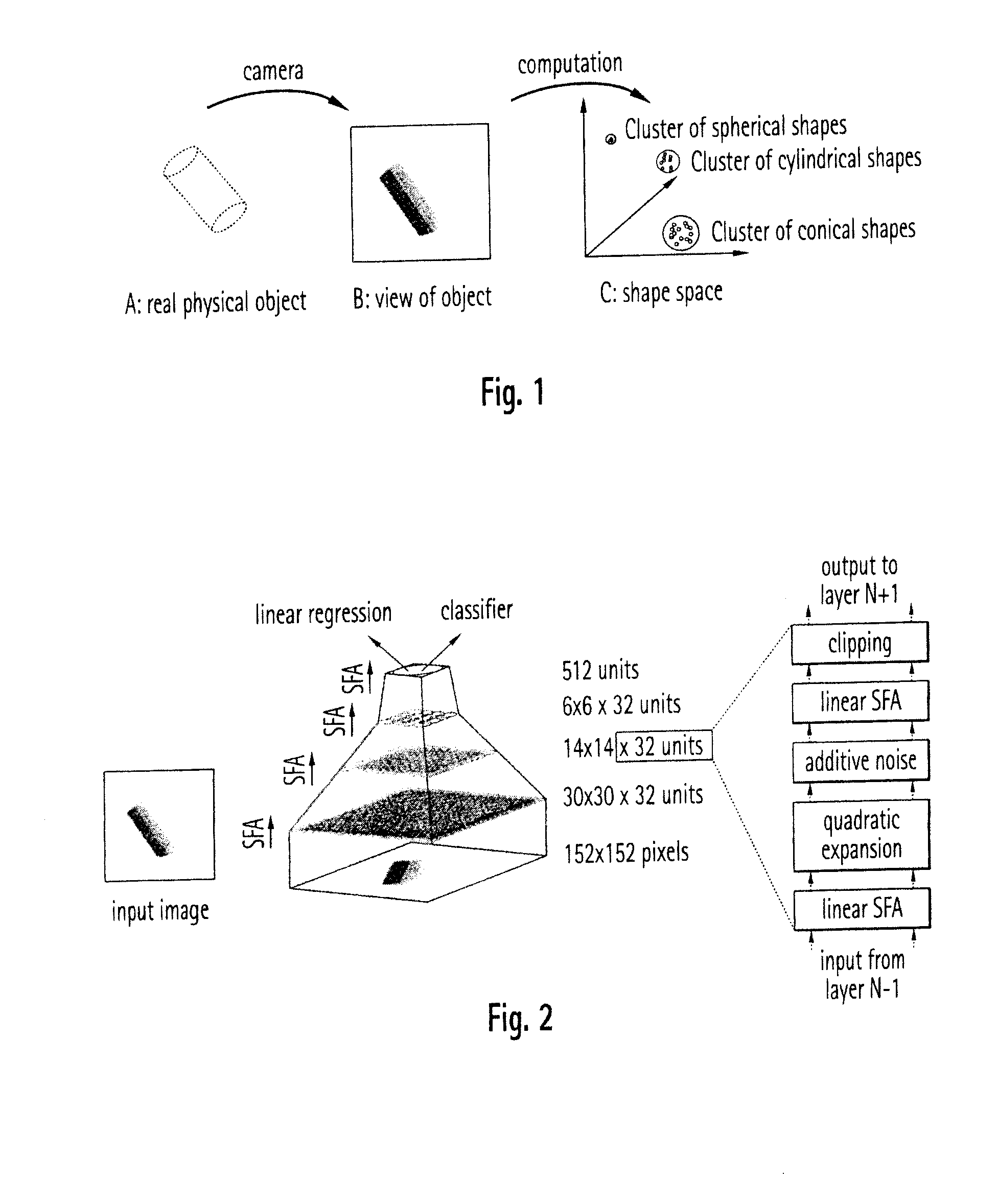
[0058]As an effect, the resulting feature representation can directly implement both view invariance, as learned from the temporal proximity of different views of identical objects during the training phase, as well as the desired similarity measure between objects. One example of such a desired similarity measure is a texture- and view-invariant shape space.
[0066]The invention is based on the existing approach of generating features automatically by computing weighted nonlinear combinations of the input channels such that the slowness objective is maximized. While this approach works well in many cases, there is no direct way of controlling the feature generation process. The invention proposes an optional mechanism to add a supervised influence on the feature generation process. If classes of specific properties are known to be relevant for the generation of the shape space, e.g., partial views showing corners or edges, these partial views can be used to train lower layers in the hierarchical model instead of (or additionally to) the full training views. In this way, the system can be trained to compute similar representations for each class of these partial views in lower layers, e.g., independently of viewing angle, lighting or texture.Application Examples for the Proposed System

Problems solved by technology

In general, the reconstruction of 3d shape from a single 2d image is ill-posed, because many 3d shapes can produce the same 2d view.
To our knowledge, however, no publications are available on the topic how view-invariant clusters relate in a shape feature space and how they could be used to characterize 3d shape.
It is not at all guaranteed that such an approach would work even for very restricted environments, as invariant object recognition by itself is very hard already.
Further disadvantage of such a specifically tailored solution include the required work to find relevant features for each case, and no obvious generalization abilities to untrained shapes.

Method used


Image

  • Robot with vision-based 3D shape recognition
  • Robot with vision-based 3D shape recognition

Examples


Embodiment Construction

[0042]The invention presents a mechanism for extracting geometric shape properties of objects from 2d images and image sequences. Additionally, the system can use visual or non-visual information for implementing a more general similarity measure. This extraction process is based on two-dimensional views but the system is largely independent of the specific view of the three-dimensional object during its operation phase. In a first phase, the training phase, the system extracts the relevant image statistics from unlabeled image sequences. The training phase uses an established algorithm based on the “slowness objective” for finding features that typically vary slowly or seldom in the training data set, e.g., Slow Feature Analysis (WisSej 2002), the trace rule (Foeldiak 1991) or temporal stability (Kayser 2001). Additional constraints guarantee that multiple non-trivial solutions (like the constant solution) are computed. The proposed system can use a single or multiple steps of opti...


PUM


Abstract

The invention relates to a method for processing video signals from a video sensor, in order to extract 3d shape information about objects represented in the video signals, the method comprising the following steps:providing a memory in which objects are stored in a 3d shape space, the shape space being an abstract feature space encoding the objects' 3d shape properties, andmapping a 2d video signal representation of an object in the shape space, the coordinates of the object in the shape space indicating the object's 3d shape.

Description

[0001]The present invention generally relates to the field of processing vision signals, i.e. signals supplied from a video or still camera. The invention especially relates to the use of such image processing for recognizing the 3d shape (or physical properties derived therefrom, such as e.g. friction coefficient) of an object present in the input field of the camera.[0002]Such 3d shape recognition may typically find application for robots having object manipulating actuators or other automated object-handling machines, which are thus enabled to adapt their behavior, especially the operation of a object manipulator (gripping force, gripping direction, . . . ) based on the recognized 3d shape of the object. In addition the robot or other machine may deduce secondary features (weight, fragility, rigidity, stiffness, . . . ) of the object from the recognized 3d shape of the object and correspondingly adapt its behavior to such secondary feature (the 3d shape of the object being the pr...

Claims


Application Information

Patent Timeline
IPC IPC(8): G06T7/00G05B15/00B25J13/08
CPCG06K9/6232G06K9/00201G06V20/64G06V10/7715G06V2201/06
Inventor FRANZIUS, MATHIASWERSING, HEIKO
Owner HONDA RES INST EUROPE
Learn More