Device comprising a multi-aperture imaging device, method for producing same and method for capturing a total field of view

a multi-aperture imaging and camera technology, applied in the direction of printers, instruments, cameras focusing arrangements, etc., can solve the problems of reduced brightness, reduced construction height, and limited miniaturization of conventional cameras, so as to achieve the effect of reducing the size of the devi

Active Publication Date: 2018-08-23
FRAUNHOFER GESELLSCHAFT ZUR FOERDERUNG DER ANGEWANDTEN FORSCHUNG EV
View PDF7 Cites 22 Cited by
  • Summary
  • Abstract
  • Description
  • Claims
  • Application Information

AI Technical Summary

Benefits of technology

[0012]In accordance with another embodiment, at least one actuator of an image stabilizer and / or focusing means is arranged such that it is arranged at least partly between two planes spanned or defined by sides of a cuboid. The sides of the cuboid are aligned in parallel to one another and to a line extension direction of the array and part of the optical path of the optical channels between the image sensor and the beam-deflecting means. A direction of the surface normal of the planes may be understood to be the thickness direction of the device. The volume of the cuboid is minimum and nevertheless comprises the image sensor, the array and the beam-deflecting means. This allows the housing to be implemented to be flat. In contrast to existing approaches, this allows the camera not to protrude in the thickness direction from the cuboid volume of the housing in any of the states.

Problems solved by technology

Conventional cameras transmit the total field of view in one channel and are limited as regards miniaturization.
Deflecting mirrors are used here which, however, are limited in their extension and thus result either in an undesired increase in the construction height or, due to vignetting of the optical path, in a reduction in the brightness.
Furthermore, when being installed in a housing of a smart phone, other parts (display, battery, electronics) may stand in the way so that the beam-deflecting means cannot deflect the optical path in the different viewing directions freely.

Method used


Image

  • Device comprising a multi-aperture imaging device, method for producing same and method for capturing a total field of view
  • Device comprising a multi-aperture imaging device, method for producing same and method for capturing a total field of view
  • Device comprising a multi-aperture imaging device, method for producing same and method for capturing a total field of view

Examples


Embodiment Construction

[0050]Before discussing below in greater detail embodiments of the present invention referring to the drawings, it is pointed out that identical elements, objects and / or structures or those of equal function or equal effect, in the different figures, are provided with equal reference numerals so that the description of these elements illustrated in different embodiments is mutually exchangeable or mutually applicable.

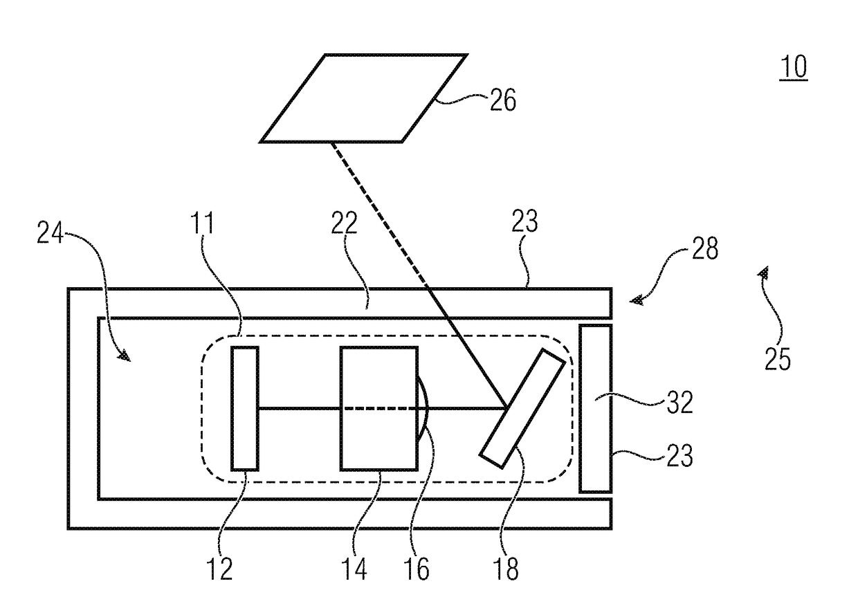
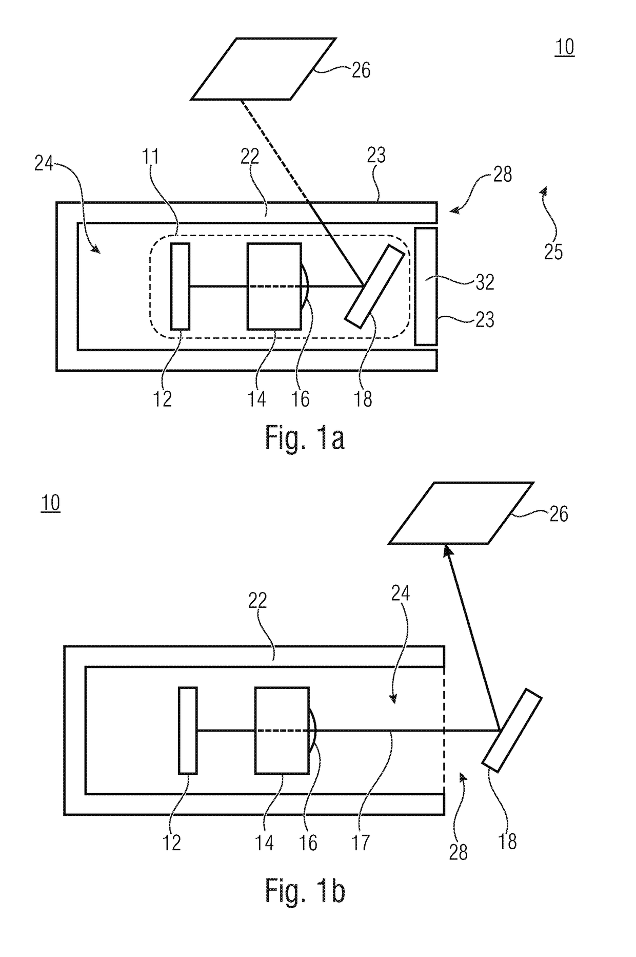
[0051]FIG. 1a shows a schematic sectional side view of a device 10 in accordance with an embodiment in a first operating state. The device 10 may be a mobile or immobile device, like a mobile phone, smartphone, mobile computer, like a tablet computer, and / or mobile music playback means.

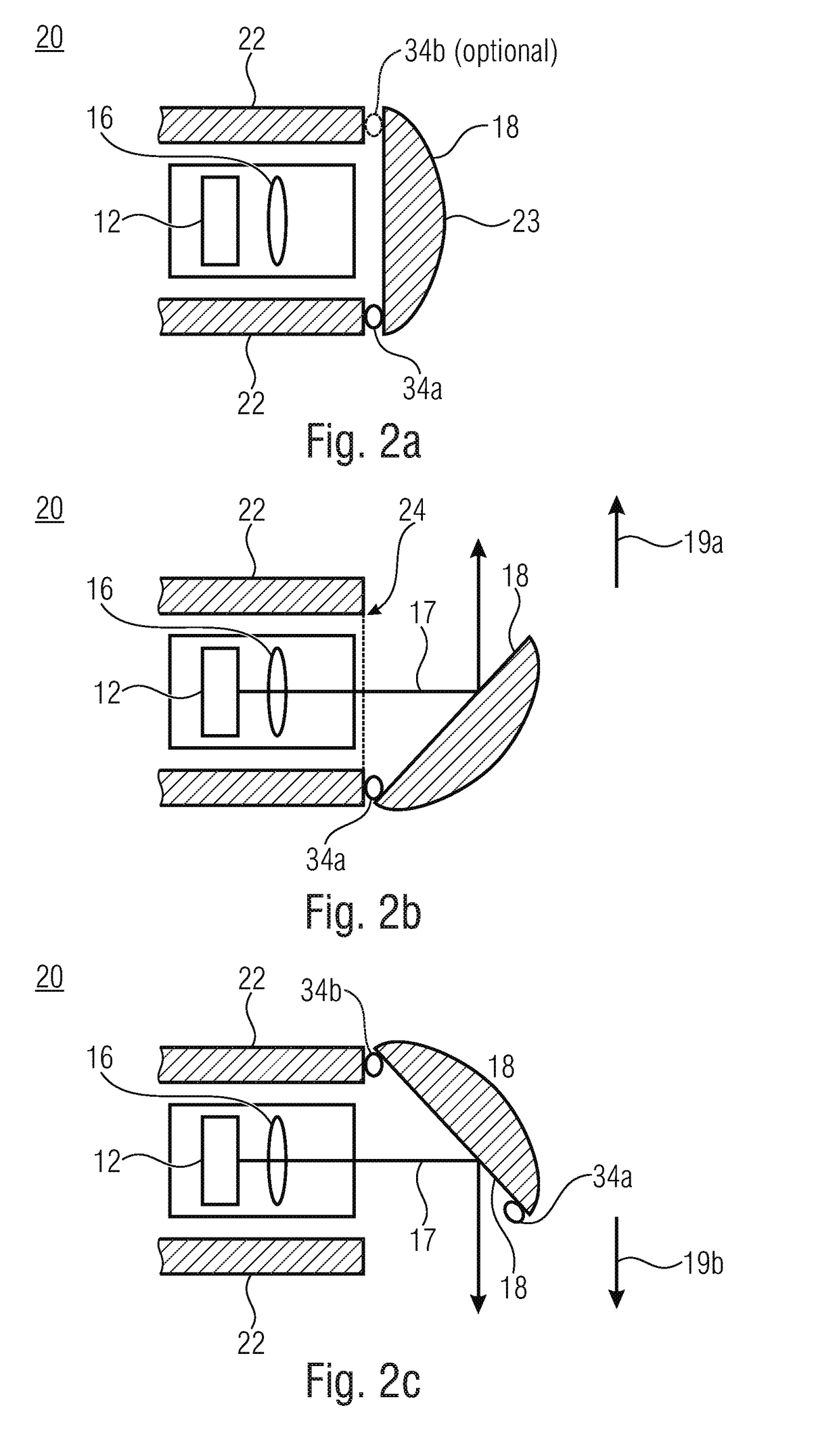
[0052]The device 10 comprises a multi-aperture imaging device 11 comprising an image sensor 12, an array 14 of optical channels 16 arranged next to one another and beam-deflecting means 18. The beam-deflecting means 18 is configured to deflect an optical path 17 of the optical channels 16...


PUM


Abstract

A device described here includes a housing and a multi-aperture imaging device. The multi-aperture imaging device includes an array of optical channels arranged next to one another and a beam-deflector for deflecting an optical path of the optical channels. In a first operating state of the device, the housing encloses a housing volume. In the first operating state of the device, the beam-deflector includes a first position within the housing volume. In a second operating state of the device, the beam-deflector includes a second position where the beam-deflector is arranged at least partly outside the housing volume.

Description

CROSS-REFERENCE TO RELATED APPLICATIONS[0001]This application is a continuation of copending International Application No. PCT / EP2016 / 075083, filed Oct. 19, 2016, which is incorporated herein by reference in its entirety, and additionally claims priority from German Application No. 10 2015 220 566.5, filed Oct. 21, 2015, which is also incorporated herein by reference in its entirety.[0002]The present invention relates to a device comprising a multi-channel imaging device, to a method for producing same, and to a method for capturing a total field of view. In addition, the present invention relates to multi-aperture imaging systems comprising a linear channel arrangement and an extendible housing.BACKGROUND OF THE INVENTION[0003]Conventional cameras transmit the total field of view in one channel and are limited as regards miniaturization. In mobile devices, such as smart phones, two cameras are used which are oriented in the sense of the surface normal of the display and opposite th...

Claims


Application Information

Patent Timeline
Patent Type & Authority Applications(United States)
IPC IPC(8): H04N5/225H04N5/232G03B17/17G03B17/04G03B5/00
CPCH04N5/2254H04N5/23238G03B17/17G03B17/04H04N5/2258G03B5/00G02B13/0065G02B13/06G02B26/0816G02B27/1066G02B27/143H04N23/45G02B5/08H04N23/55G02B27/106G03B13/32G03B3/10H04N23/698
Inventor WIPPERMANN, FRANKLANGE, NICOLASPABST, OLIVER
Owner FRAUNHOFER GESELLSCHAFT ZUR FOERDERUNG DER ANGEWANDTEN FORSCHUNG EV
Why Eureka
Try Eureka