Drilling tool for chip removing machining as well as a loose top therefor

a technology of drilling tool and loose top, which is applied in the direction of twist drill, manufacturing tools, cutting inserts, etc., can solve the problems of increasing the cost of material consumption, and increasing the difficulty of industrial series manufacturing, so as to improve the drilling effect, reduce the consumption of expensive materials, and improve the inherent elasticity of branches

Active Publication Date: 2014-09-23
SANDVIK INTELLECTUAL PROPERTY AB
View PDF47 Cites 18 Cited by
  • Summary
  • Abstract
  • Description
  • Claims
  • Application Information

AI Technical Summary

Benefits of technology

[0014]The present disclosure aims at obviating the above-mentioned disadvantages of the drilling tool known by EP 1013367 and at providing an improved drilling tool. Therefore, an object is to provide a drilling tool having a loose top that in its entirety is held reliably clamped between the branches of a jaw in the basic body of the tool. In doing so, the inherent elasticity of the branches is to be utilized in an expedient way for providing an optimal grip on the loose top. Another object is to provide a drilling tool, the loose top of which has a minimal length, and thereby a minimal volume, in relation to its diameter. This can reduce the consumption of expensive material to a minimum in connection with manufacture. A further object is to provide a drilling tool with a basic body that can transfer great torques to the loose top. Furthermore, the drilling tool should allow a quick, simple and convenient replacement of the loose top, without other means than a simple key and without the basic body necessarily having to be removed from the driving machine. A factor to guarantee smooth replacements is that the branches should present only a moderate resistance to the turning-in of the loose top into the jaw of the basic body, in spite of the fact that the ability of the branches to hold the loose top reliably clamped should be good. A further object is to provide a drilling tool in which the loose top is centered, and retains its centricity, in an accurate way in relation to the basic body.
[0017]The two branches that delimit a jaw of the basic body have their greatest bending capacity, and thereby their optimal gripping capacity, in the area of the free ends thereof rather than in the vicinity of the rear ones. By placing the side contact surfaces of the loose top in the immediate vicinity of the front end of the loose top, a powerful grip or pinch along the front portion of the loose top adjacent to the cutting edges can be obtained. For a given axial length of the loose top, the branches can furthermore be given a optimized design that, in addition to improving the proper tightening effect, also improves the ability of the branches to transfer torque, in that the tangential contact surfaces of the branches can be made as long as the loose top. In addition, the placement and design of the cooperating surfaces afford a number of further advantages that are accounted for later in this document.

Problems solved by technology

However, for differing reasons, attempts to manufacture such loose-top tools on an industrial scale have not been successful, among other things, because the slot opens not only axially but also laterally and in such a way forms a trap in which the removed metal chips may entangle themselves and entail difficulties, for example, chip jamming.
However, these loose-top tools are associated with problems and disadvantages difficult to master, which makes industrial series manufacturing more difficult.
One disadvantage is that the axial length of the loose top is considerable in relation to the diameter.
Because of this, the total volume of the loose top becomes comparatively large and causes expensive consumption of material in the manufacture.
Another disadvantage is that the pinch or grip between the loose top and the branches is located at the rear parts of the branches, which is behind the requisite axial support surfaces, where the ability of the branches to deflect is minimal.
Therefore, the more the branches are separated during clamping, the greater becomes the risk that the front parts of the branches lose contact with the loose top.
In the extreme case, it is even possible that gaps arise between the outside of the loose top and the inner support surfaces of the front parts of the branches.
Another one of several further disadvantages, in addition to complicated manufacture, is that cooperating pairs of axial contact surfaces of the loose top and the corresponding axial support surfaces of the basic body are rather small and peripherally located.
In such a way, the axial force transmission between the loose top and the basic body may become unreliable, and unbalances may arise and jeopardize the centering of the loose top.
A disadvantage of the drilling tool of EP 1013367 is, however, that the grip of the branches on the loose top risks becoming weak and unreliable.
Only the rear portion of the loose top is held clamped between the branches, while the front portion thereof—in which the cutting forces act strongest—lacks efficient clamping.
Another negative consequence of the branches having a limited length is that the tangential contact surfaces, which have the purpose of transferring torque to cooperating surfaces in the pockets of the loose top, get a limited area.
In such a way, the surface pressure may become high and cause deformation damage.
Furthermore, there is a risk that the loose top will be difficult to manufacture with precision that allows the loosed top to be centered in an accurate way.
Accordingly, in practice it is impossible to precision-grind the side contact surfaces positioned in the interior of the pockets.

Method used


Image

  • Drilling tool for chip removing machining as well as a loose top therefor
  • Drilling tool for chip removing machining as well as a loose top therefor
  • Drilling tool for chip removing machining as well as a loose top therefor

Examples


Embodiment Construction

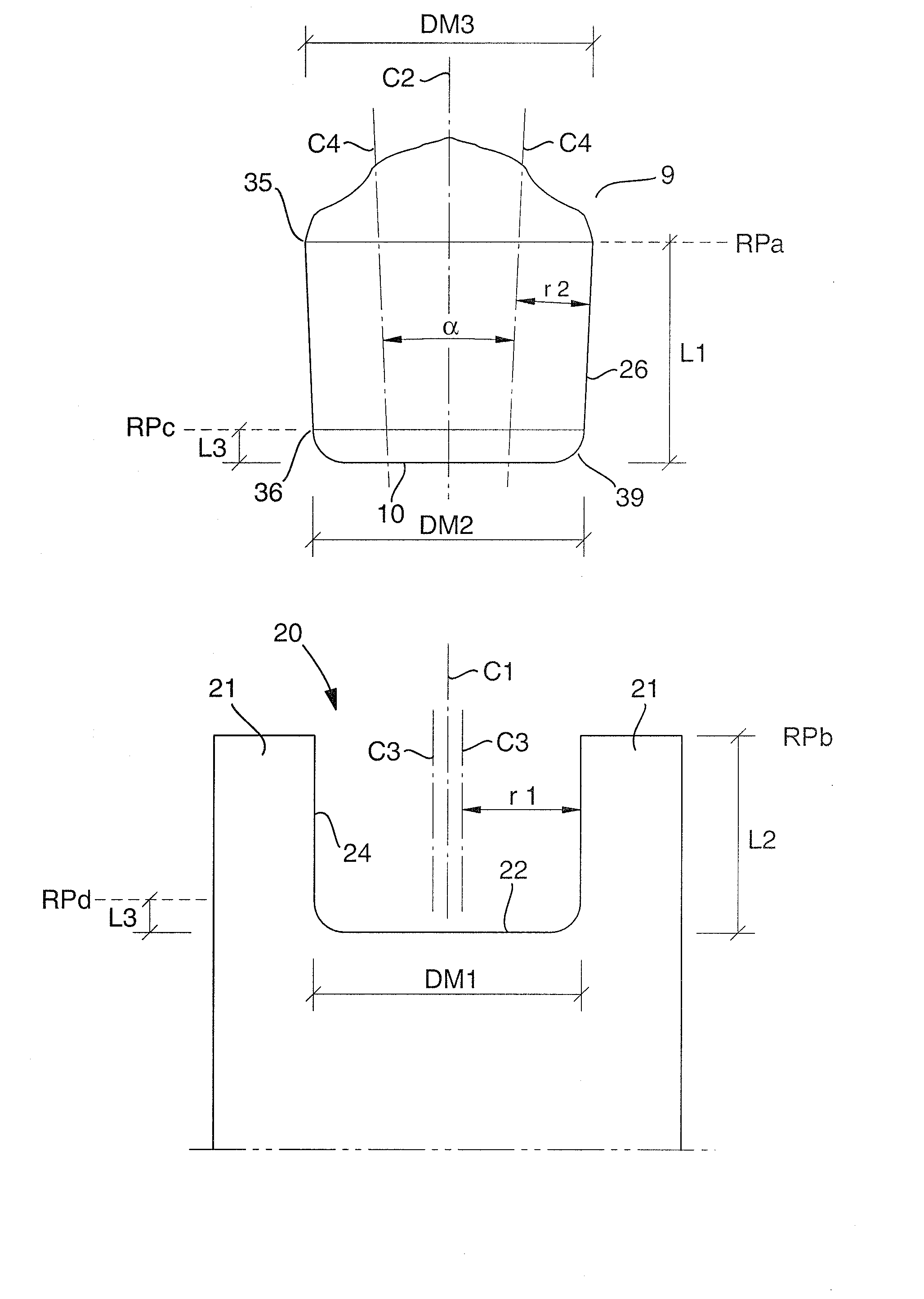
[0040]In the following description and the claims, a number of cooperating pairs of surfaces of the basic body and the loose top, respectively, will be described. When these surfaces are present on the basic body, the surfaces are denominated “support surfaces”, while the corresponding surfaces of the loose top are denominated “contact surfaces” (for example, “axial support surface” and “axial contact surface”, respectively). Furthermore, it should be pointed out that the loose top includes a rear end in the form of a plane surface, which serves as an axial contact surface for pressing against an axial support surface in the basic body. Depending on the context, this surface will be denominated either “rear end” or “axial contact surface”. In the drawings, the cooperating surfaces contacting each other in the operative state of the drilling tool are shown by similar surface patterns.

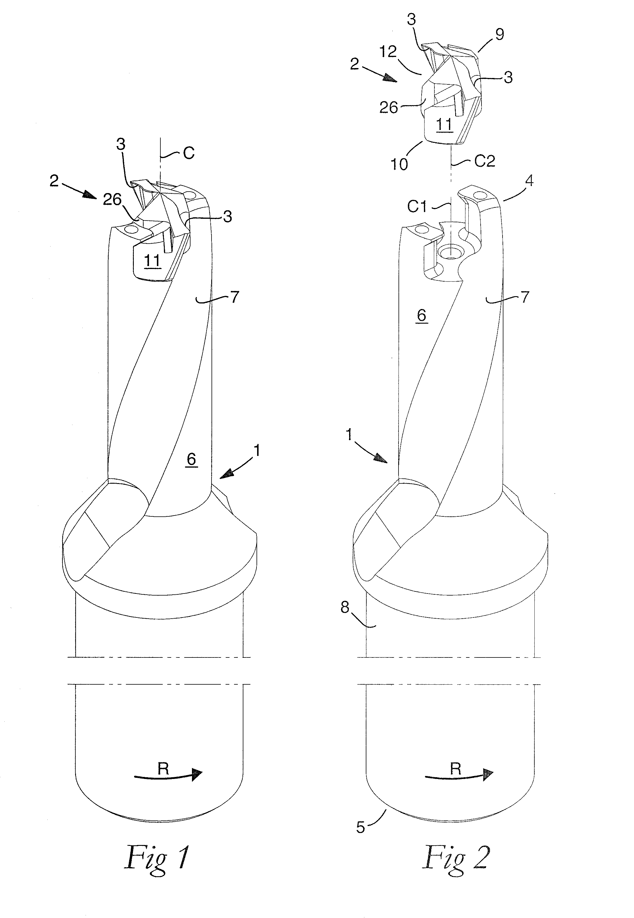
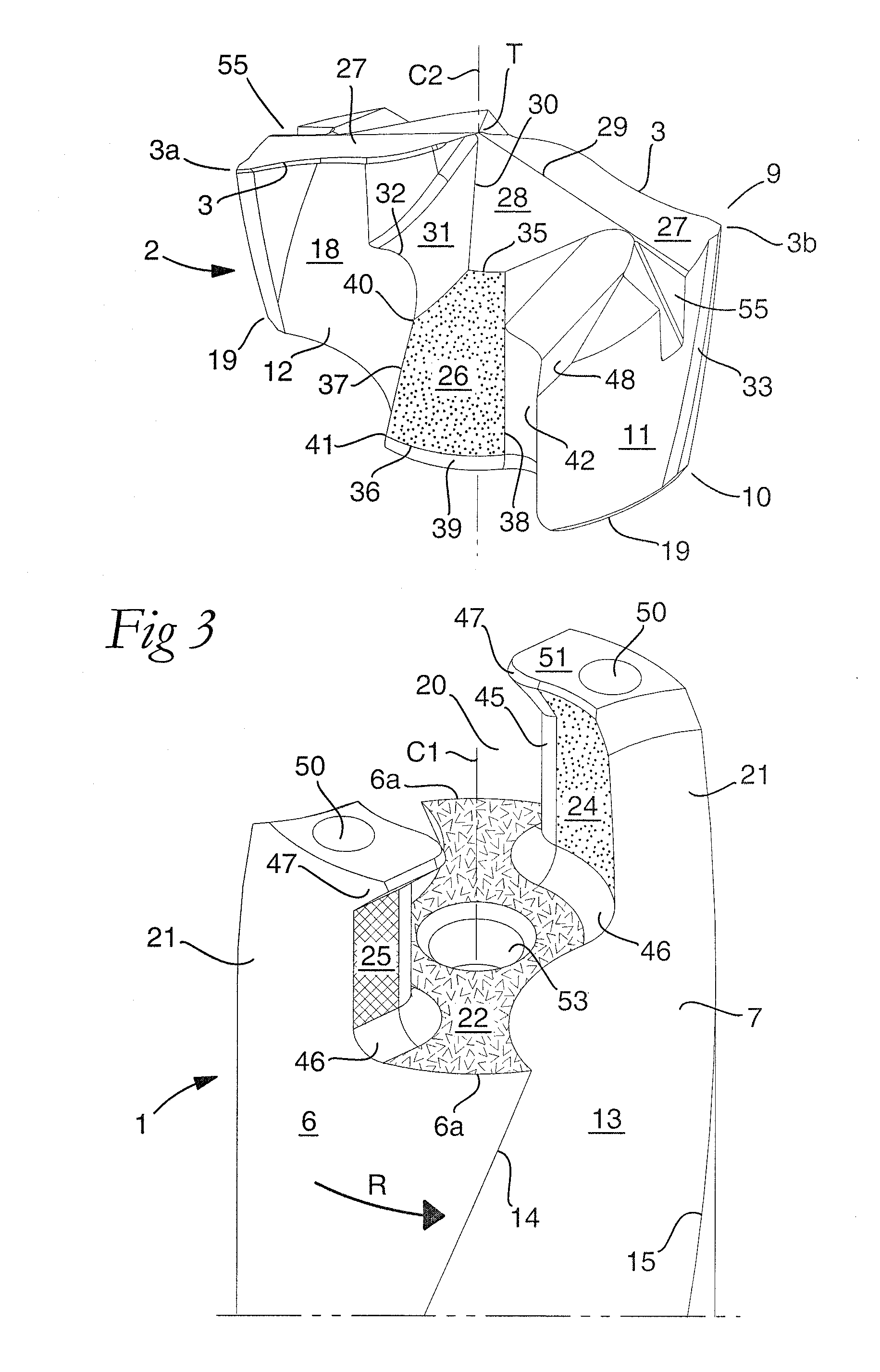
[0041]The drilling tool shown in FIGS. 1 and 2 is in the form of a so-called twist drill, comprises a...


PUM

PropertyMeasurementUnit
radial distanceaaaaaaaaaa
γaaaaaaaaaa
diametrical dimensionaaaaaaaaaa

Abstract

A drill of the loose top type, which is composed of a basic body and a replaceable loose top. In the front end of the basic body, a jaw is formed, which is delimited by two elastically bendable branches and an intermediate axial support surface, and in which the loose top can be securely pinched by inner support surfaces of the branches being resiliently pressed against side contact surfaces of the loose top. The two side contact surfaces of the loose top extend rearward from clearance surfaces that are included in the front end of the loose top. By forming the diametrical dimension between opposite side contact surfaces greater nearer the front end of the loose top, the branches of the jaw securely pinch the loose top in the area of the front ends thereof, where the branches have their maximal bending capacity.

Description

CROSS-REFERENCE TO PRIOR APPLICATION[0001]This application claims priority to Swedish Application No. 0900846-7 filed Jun. 23, 2009, which is incorporated by reference herein.TECHNICAL FIELD[0002]In a first aspect, this disclosure relates to a drilling tool intended for chip removing machining and of the type that includes a basic body having front and rear ends and an envelope surface that includes two countersunk chip flutes. The envelope surface is concentric with a center axis around which the basic body is rotatable in a given direction of rotation. The tool further includes a loose top that includes front and rear ends, where the rear end serves as an axial contact surface. The loose top further includes an envelope surface that is concentric with a center axis and includes two countersunk chip flutes between which two bars projecting radially from a central core are delimited. The front end of the bars include a cutting edge each and a number of clearance surfaces positioned ...

Claims


Application Information

Patent Timeline
Patent Type & Authority Patents(United States)
IPC IPC(8): B23B51/02
CPCB23B51/02B23B2251/50B23B2205/02B23B2251/02Y10S408/713Y10T408/892Y10T408/90987Y10T408/907Y10T408/9098Y10T408/9097
Inventor AARE, MAGNUS
Owner SANDVIK INTELLECTUAL PROPERTY AB
Why Eureka
Try Eureka