Modular passive refrigeration container

a refrigeration container and module technology, applied in the field of modules, can solve the problems of inability to pump around or evaporate coolant, dependent on a source of energy, and inability to effectively move active refrigeration containers,

Active Publication Date: 2015-04-23
ETABEN FRANZ COLRUYT
View PDF3 Cites 16 Cited by
  • Summary
  • Abstract
  • Description
  • Claims
  • Application Information

AI Technical Summary

Problems solved by technology

Such cooling systems have the disadvantage that they are dependent on a source of energy, in particular an electrical power source, optionally in combination with a diesel engine.
As a result, active refrigeration containers are essentially immobile, expensive and maintenance prone.
Thus, it is not possible to pump around or to evaporate a coolant.
By the use of intensive large numbers of said passive refrigeration containers at the distribution center and by treatment thereof with manipulation devices such as forklift trucks, both the outer wall (the housing) as the inner wall are often crushed, with the result that the intermediate insulation is compressed and parti

Method used


Image

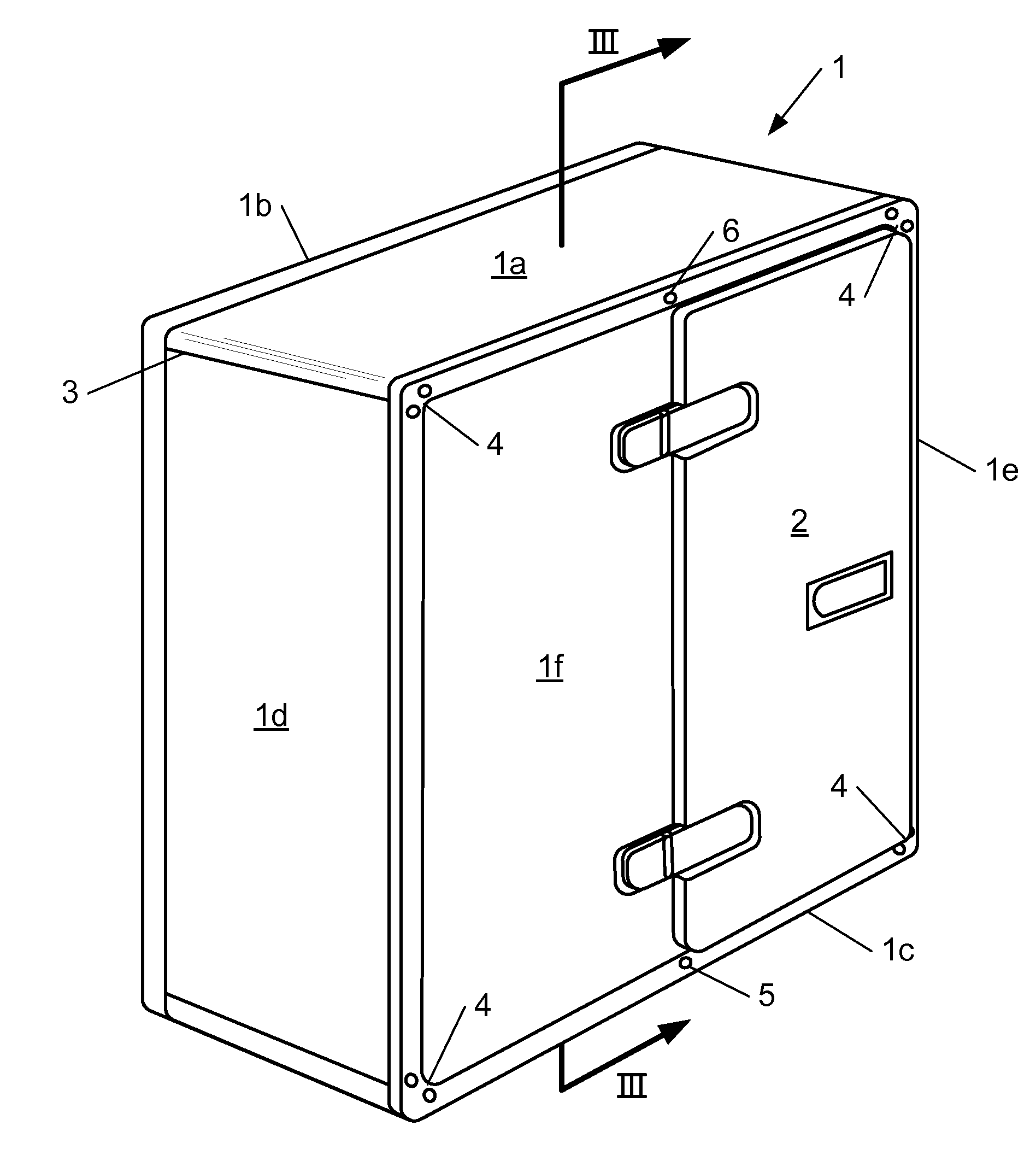
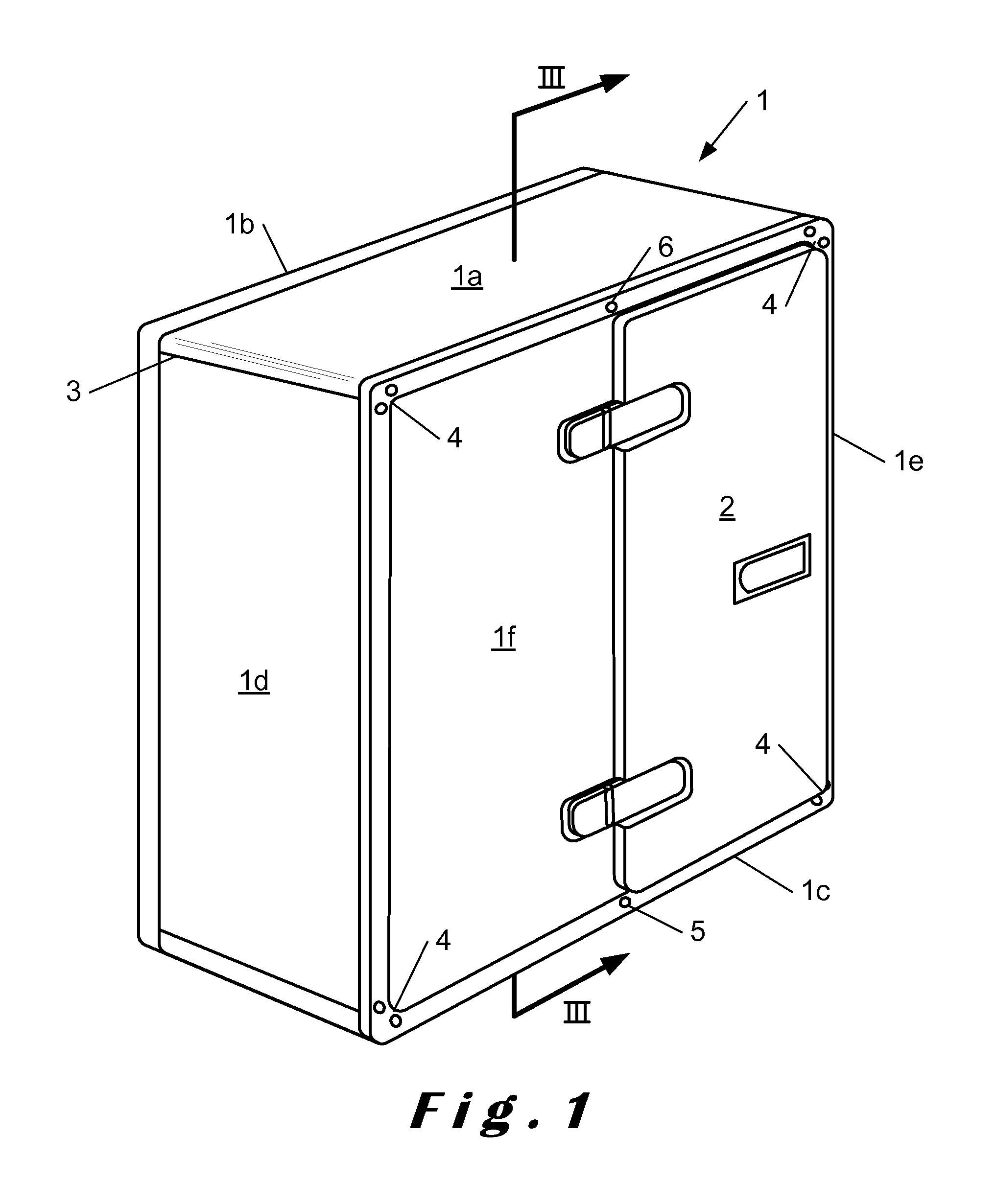
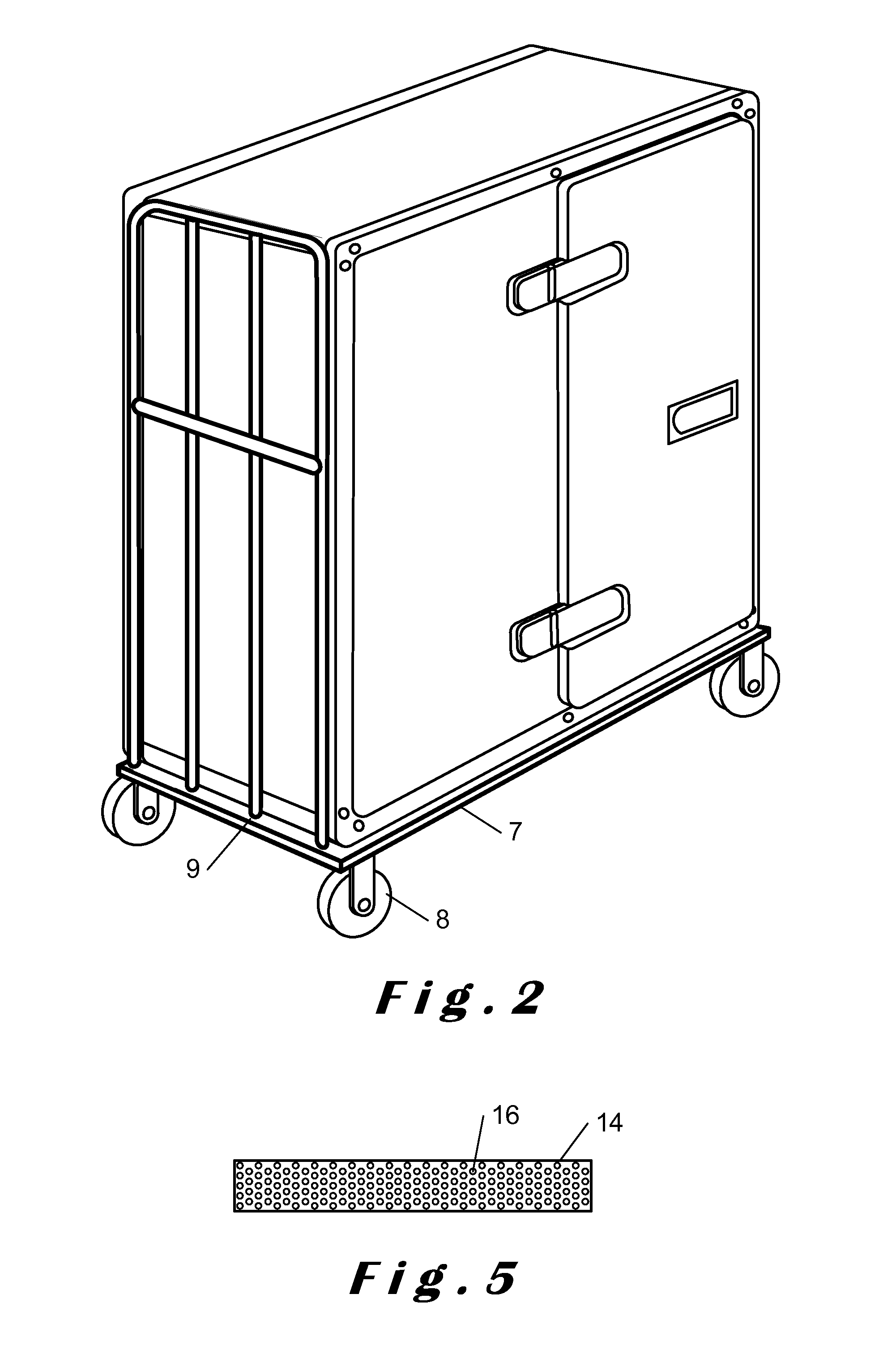
  • Modular passive refrigeration container
  • Modular passive refrigeration container
  • Modular passive refrigeration container

Examples


first embodiment

[0028] three plate-shaped hollow cooling segments form a C-shaped cooling element, in which two plate-shaped cooling segments are arranged parallel to each other and connected by a third which extends perpendicularly between the plate-shaped cooling segments placed parallel to each other.

[0029]According to an alternative embodiment, the third plate-shaped cooling segment, which extends perpendicularly between the plate-shaped cooling segments placed parallel to each other, is divided into two separate hollow spaces which are not in fluid communication with each other. In an embodiment, in which the third plate-shaped cooling segment together with the first and second cooling segment forms a hollow space, a C-shaped cooling element arises with two L-shaped hollow compartments, each of which should be filled separately with coolant, in particular binary ice. In a preferred embodiment, this third cooling segment is a cooling segment, which is placed vertically in the refrigerated conta...

second embodiment

[0030] three plate-shaped hollow cooling segments form a cooling element, wherein each of the three plate-shaped hollow cooling segments are connected to each other on two sides with the edge of this side, or, in other words, with the three plate-shaped hollow cooling segments each perpendicular to each other.

[0031]According to a further embodiment, the cooling element comprises at least one further plate-shaped cooling segment which is connected to one or more of the edges with the at least three hollow plate-shaped cooling segments.

[0032]According to one embodiment, the further plate-shaped element is a hollow plate-shaped cooling segment which is connected with one or more of its edges with the other present hollow plate-shaped cooling segments together forming one hollow space. As a result, a cooling element is obtained which comprises four plate-shaped hollow cooling segments. According to one embodiment, said four hollow plate-shaped cooling segments form a □-shaped cooling el...


PUM

PropertyMeasurementUnit
Lengthaaaaaaaaaa

Abstract

The invention relates to a modular passive refrigeration container for the cold storage and transport of goods, especially fresh produce and deep-frozen goods as well as to a method for the assembly of such a modular passive refrigerated container, comprising at least: (i) a cooling element, suitable for binary ice as coolant, comprising at least three plate-shaped hollow cooling segments, wherein the plate-shaped cooling segments define at least a portion of the refrigeration space, (ii) an insulation material in plate form, and (iii) a housing, suitable for receiving said cooling element and said insulating material in plate form, wherein said cooling element is removably surrounded by said housing, and wherein a space between the said cooling element and said housing is at least partially filled with said insulating material which is reversibly connected with either said housing or said cooling element or both.

Description

INTRODUCTION[0001]The invention relates to a modular passive refrigeration container for the refrigerated storage and transport of goods, in particular fresh and deep frozen products, as well as to a method for the assembly of such modular passive refrigeration container.BACKGROUND OF THE INVENTION[0002]Refrigerated transport is required to maintain a cold chain for fresh produce such as flowers, vegetables, fruits, milk products, meat, fish and poultry, frozen foods such as ice cream and other temperature sensitive products such as chemicals, biological agents, explosives, etc. which have to be at least partly refrigeratedly transported. The refrigerated transport includes transport by light and heavy trucks, trains, containers, ships, aircraft, etc.[0003]Distribution networks typically make use of such a refrigerated transport. Refrigerated goods are stocked in refrigerated refrigeration containers, conveyed to the shops and unloaded into the refrigerated space of the respective s...

Claims


Application Information

Patent Timeline
IPC IPC(8): F25D3/06F25D23/00F25D11/00
CPCF25D3/06F25D23/006F25D11/003F25C2301/002F25D2303/082F25D2201/126F25D2201/14F25D2303/081F25D2303/08222F25D2331/804Y10T29/49359G01B9/0207G01B11/14
Inventor COUSAERT, ERIKNOELS, CARENMERCKX, KOENVANVERRE, WIMVAN MULDERS, JOACHIM
Owner ETABEN FRANZ COLRUYT
Why Eureka
Try Eureka