Reciprocating arm motion walker

a walking arm and recoil technology, applied in walking aids, gymnastics, physical therapy, etc., can solve problems such as reducing ue management, and achieve the effects of reducing instability and associated fall risk, preventing foot contact with wheels, and facilitating turning

Active Publication Date: 2018-09-06
NEUROMOBILITY LLC
View PDF10 Cites 18 Cited by
  • Summary
  • Abstract
  • Description
  • Claims
  • Application Information

AI Technical Summary

Benefits of technology

[0045]The torso bar can be positioned for fit and function. Consistent bodily positioning relative to the frame provides for safer turning, and prevents foot contact with wheels. Connection of the torso bar to the frame could include spring loaded or other mechanisms in order to enable a selected amount of freedom of movement between the user with secured torso bar and the frame. This may be beneficial when using the device on uneven terrain or to accommodate gait patterns with excessive vertical displacement of the center of gravity.
[0046]A walker is provided with a preferred wheel configuration including standard wheels in the front to prevent side to side movement of the device when arms are moving. Swivel wheels in the rear enable turning. The device is turned by moving the rear frame away from the direction of the turn instead of moving the front end of the frame in the direction of the turn. Consistent improved positioning of the body relative to the device in conjunction with wheel configuration may reduce instability and associated fall risk related to traditional rollator use with excessive UE weight bearing and device too far away from the body. A device is provided which can be used with standard wheels in the front and legs without wheels in the rear. A device is provided which can be used with casters in the front and standard wheels in the rear. This configuration may be desirable when UE support assemblies are statically positioned. A device is provided which enables efficient integration of any combination of UE support surface (gripping surfaces, forearm support). The device provides for straight or curved rails. Curved rails enable rotatory shoulder motion and may be particularly useful with incorporation of forearm supports. A rollator with this configuration could be uniquely used for activities such as outdoor rollator walking similar to racewalking. Exaggerated UE movement when forearms are supported encourages enhanced trunk rotation when walking with a railed device. This type of training may be particularly beneficial for the PD population. A device with two forearm supports which enables movement of at least one UE provides a device which enables enhanced maneuverability and functionality when bilateral forearm support is desirable.
[004...

Problems solved by technology

The technical problem is how to reduce UE management o...

Method used


Image

  • Reciprocating arm motion walker
  • Reciprocating arm motion walker
  • Reciprocating arm motion walker

Examples


first embodiment

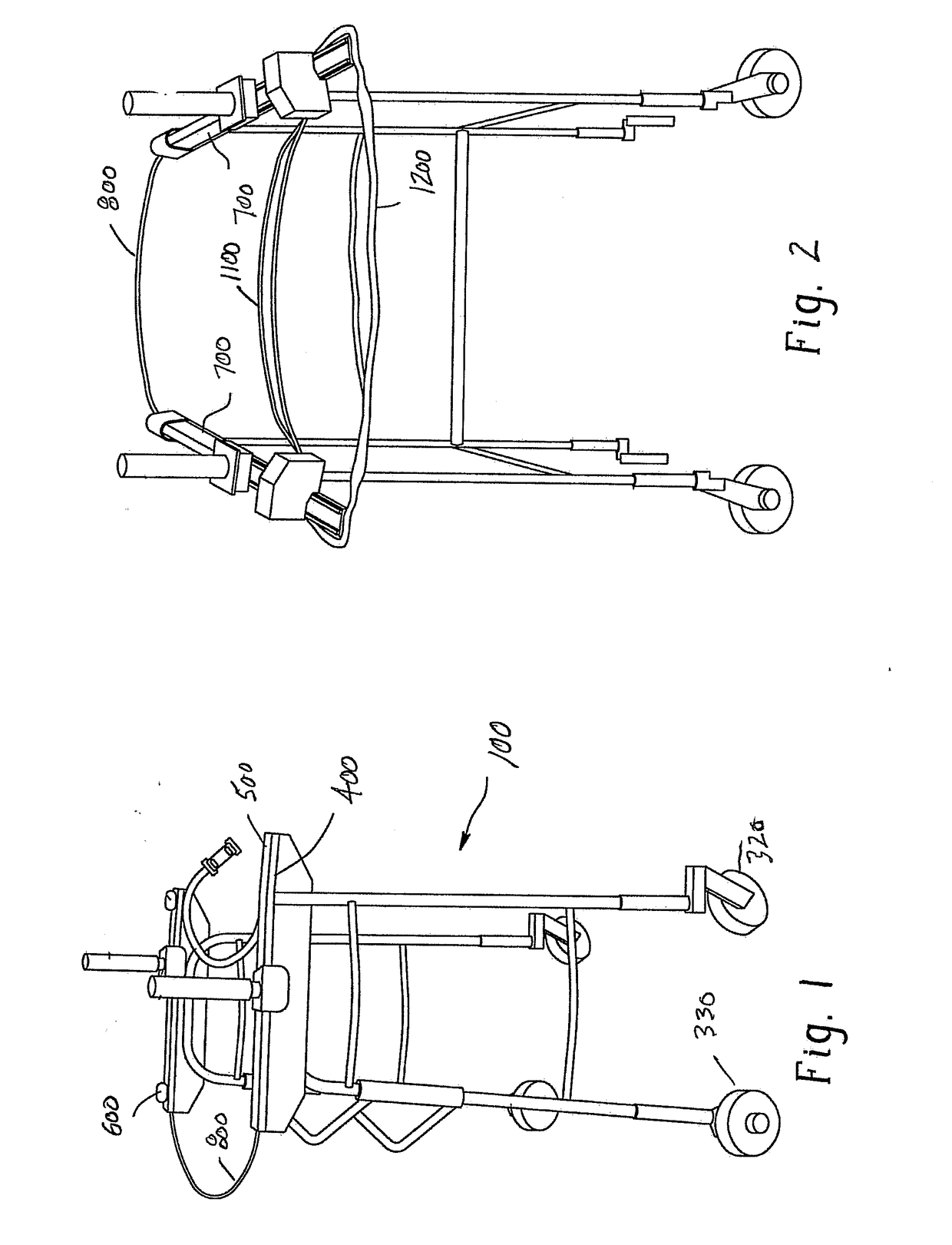
[0076]A standard aluminum walker frame has been incorporated in the first embodiment and is shown in FIG. 1 (side view) and FIG. 2 (posterior view). The walker includes two side frames 100 (110 front, 120 rear) connected anteriorly with bars 200, creating a 3-sided walker. Each side frame 110, 120 has two legs, one anteriorly 110 and the other posteriorly 120 disposed or positioned. The height of the walker can be adjusted (for example, a conventional snap pin is located at the distal end of the walker leg and the snap pin inserts into one of several spaced holes in the fitting which attaches to the walker leg). Interchangeable fittings 300 typically have at their terminus standard wheels, swivel / caster wheels, glides, or rubber tips. Standard wheels 330 are shown on the front legs of the device in the illustration, and caster wheels 320 are shown in the back. This is the preferred embodiment.

[0077]Along the upper surface of each of the side frames, a generally L-shaped member such ...

second embodiment

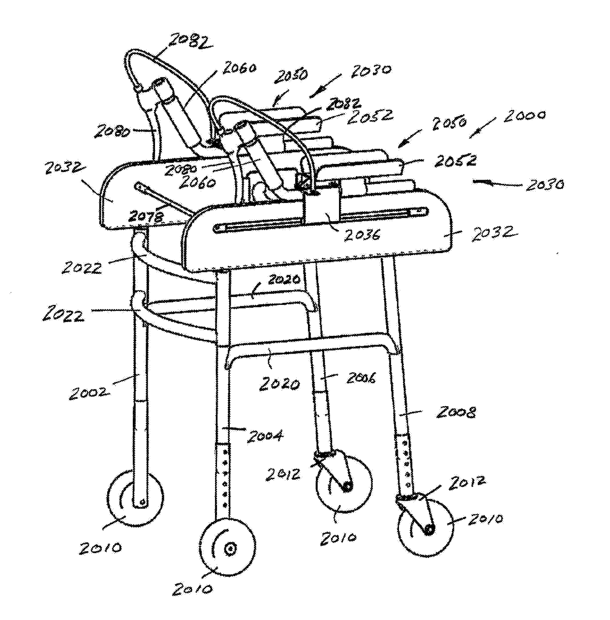
[0092]FIGS. 6-10 illustrate the reciprocating arm movement wheeled walker which incorporates a standard walker frame and a preferred type of timing belt / pulley linkage to create reciprocating UE motion. In FIG. 6, a wheeled walker 2000 includes first, second, third, and fourth legs 20022004, 2006, 2008. Each of the legs 2002-2008 includes a wheel 2010 at a lower end. In the illustrated embodiment of FIG. 6, the rear wheels 2010 are caster mounted at 2012 for rotation about a vertical axis as is conventionally known in the art. Further, each of the legs 2002-2008 may be height adjustable. Again, details of the height adjustability are well known in the art, although one manner of providing adjustment is to include concentric tubes that include a snap pin received through one of a series of axially spaced openings. The snap pin is mounted to one of the tubes and includes a head or button portion that protrudes through one of the axially spaced openings to define the position (and thus...

third embodiment

[0107]FIGS. 11A and 11B illustrate the disclosure. An alternate method of achieving mobile assemblies, of connecting a push pull cable linkage, and attaching the support surface assemblies is incorporated. The ends 3316 of torso bar 3310 are positioned vertically and are secured in clamp 3314 which attaches to the rear portion of each side of the frame. Forearm support assemblies 3318 are capable of being adjusted vertically and fore / aft (see adjustment openings in vertically aligned plates 3332) to allow the support platform to be raised and lowered, and to be mounted forwardly and rearwardly as desired. The base of each plate is secured in an aluminum U channel 3320. One or two grip handles can variably be secured to the U channel instead of the forearm assembly. On each side frame, an L-shaped length of steel 3324 is placed upon the top rail. The frame of the drawer slider 3322 is securely mounted on the steel surface. The U channel is securely mounted to the sliding component of...


PUM


Abstract

A wheeled ambulatory aid for mobility and training which is advanced via bodily contact. Reciprocating UE movement is enabled and reciprocating gait patterns can be performed. The patient mobility aid includes a frame, and at least first and second wheels operatively secured to and supporting the frame for selective rolling movement. First and second support assemblies are located on first and second sides of the frame, respectively. A reverse motion linkage operatively associated with the first and second support assemblies, the reverse motion linkage including a first state configured to provide independent between the first and second support assemblies, and a second state configured to provide interrelated movement between the first and second support assemblies to create symmetrical out of phase reciprocating UE movement. Support assemblies can variably be statically positioned.

Description

[0001]This application is a continuation-in-part of and claims the priority benefit of PCT / US2016 / 060411, international filing date of Nov. 3, 2016, which claims the priority benefit of U.S. provisional application Ser. No. 62 / 250,291, filed Nov. 3, 2015, and U.S. utility patent application Ser. No. 14 / 719,311, filed May 21, 2015, the disclosures of each of which are expressly incorporated herein by reference. This disclosure is directed to wheeled devices used for ambulatory support. Assistive devices such as walkers, rollators, and wheeled devices used for various forms of walking training are railed devices used as mobility aids to improve balance and to reduce lower extremity (LE) loading, for gait and other physical rehabilitation, as therapeutic devices, and for neurorecovery of locomotor function. The interest in physical, physiological, and functional effects of using walkers and rollators and the use of these devices for therapeutic purposes is increasing (O'Hare et al, 201...

Claims


Application Information

Patent Timeline
IPC IPC(8): A61H3/04
CPCA61H2003/006A61H2003/046A61H3/04A61H3/008A61H2201/1276A61H2201/1635A61H2203/0406A61H2205/06A63B23/035A63B23/1263
Inventor JOHNSON, CYNTHIA LOUISE
Owner NEUROMOBILITY LLC
Why Eureka
Try Eureka