Impeller

Inactive Publication Date: 2018-09-06
COOLER MASTER CO LTD
View PDF53 Cites 5 Cited by
  • Summary
  • Abstract
  • Description
  • Claims
  • Application Information

AI Technical Summary

Benefits of technology

[0023]As mentioned above, the impeller of the disclosure includes a wheel hub and a plurality of blades. Each of the blades has a blade root, and the blade connects to the wheel hub through the blade root. The blades have different lengths, and each blade has an included angle between the blade root and the wheel hub. T

Problems solved by technology

Moreover, to decrease the generated noise and the abnormal sound as the fan rotates is also a very important issue.
If the rotating heat-dis

Method used


Image

  • Impeller
  • Impeller
  • Impeller

Examples


Example

[0033]The present disclosure will be apparent from the following detailed description, which proceeds with reference to the accompanying drawings, wherein the same references relate to the same elements.

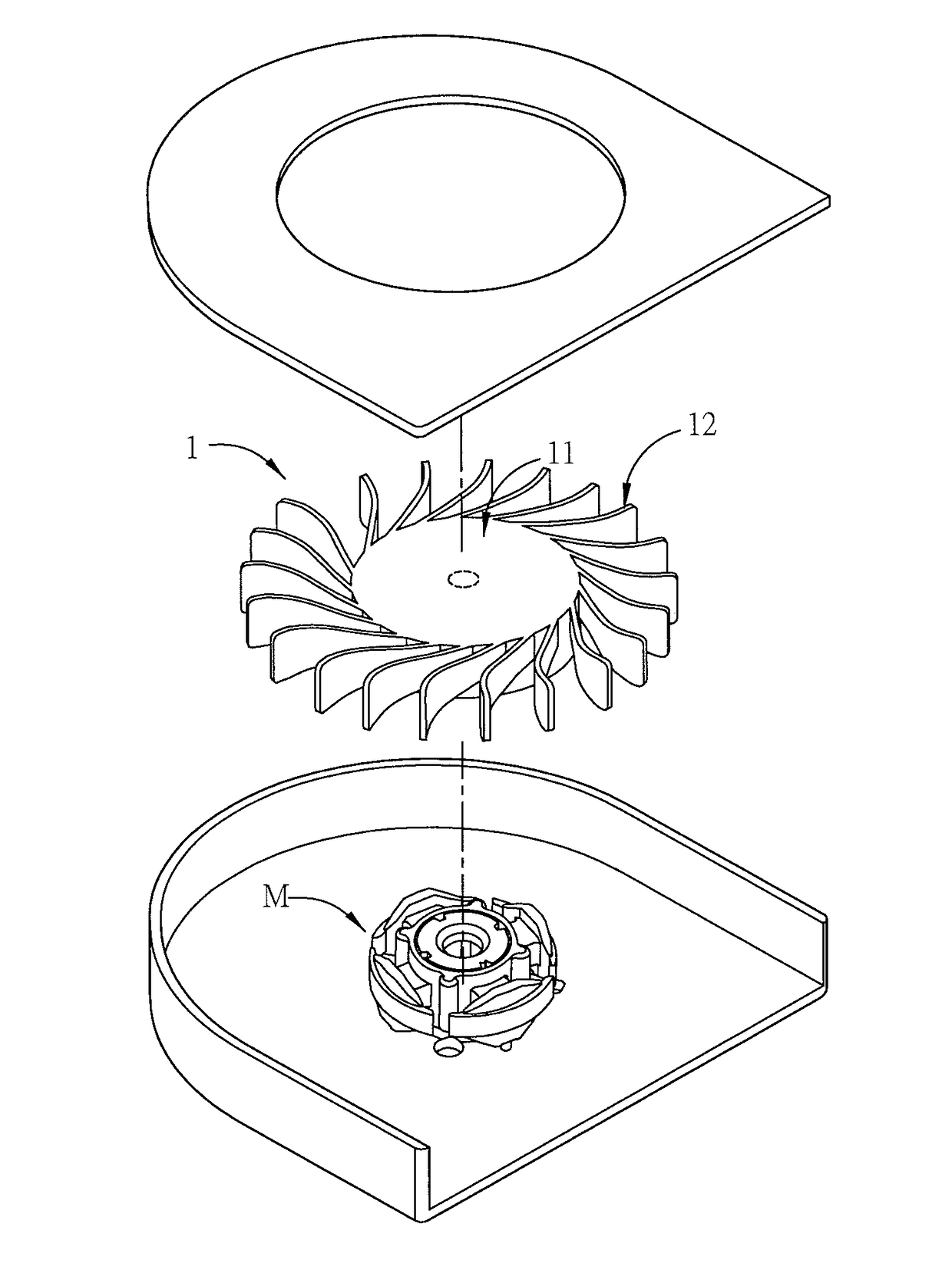
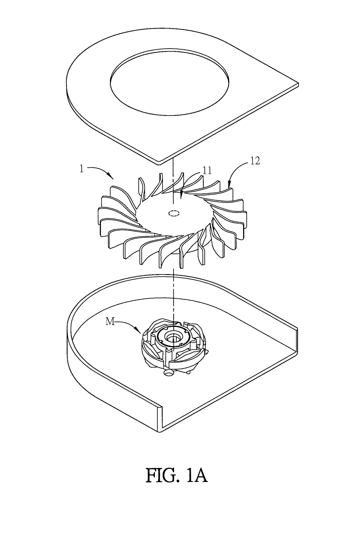
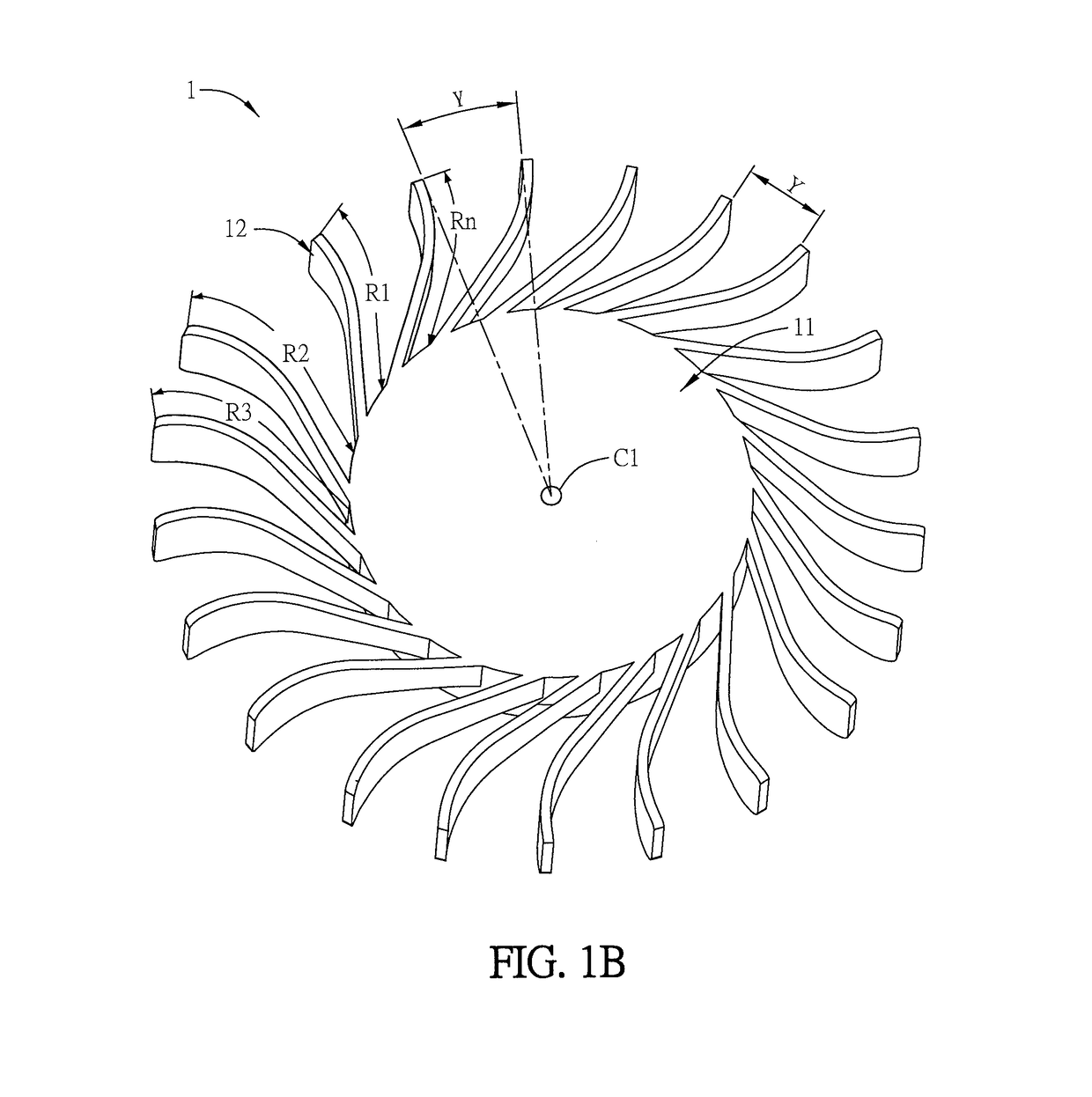
[0034]FIG. 1A is a schematic diagram of a fan according to an embodiment of the disclosure, FIG. 1B is a schematic diagram of an impeller according to an embodiment of the disclosure, and FIGS. 1C and 1D are top views of the impeller of FIG. 1B. To be noted, the lengths and shapes of the blades and the impeller 1 of FIGS. 1A to 1D are for illustrations only, and they can be modified based on the environment and the heat source of the target electronic device.

[0035]As shown in FIG. 1A, the impeller 1 is configured in a heat-dissipating fan. The fan can be applied to dissipate heat of any electronic device such as, for example but not limited to, a computer, power device, CPU, VGA, IC, mainboard, or lamp, which can generate a lot of heat. The fan can be configured to force the air flow...


PUM


Abstract

An impeller includes a wheel hub and a plurality of blades. The blade has a blade root, and the blade connects to the wheel hub through the blade root. The blades have different lengths. Each blade has an included angle between the blade root and the wheel hub, and the included angles of the blades are different. A centroid of the blades is located at an axis center of the impeller. The impeller is further configured with a blade reinforcement structure.

Description

CROSS REFERENCE TO RELATED APPLICATIONS[0001]This Non-provisional application claims priority under 35 U.S.C. § 119(a) on Patent Application No(s). 201720192846.9 filed in People's Republic of China on Mar. 1, 2017, the entire contents of which are hereby incorporated by reference.BACKGROUNDTechnology Field[0002]This disclosure relates to an impeller and, in particular, to an impeller having blades with different lengths and included angles.Description of Related Art[0003]The heat dissipation device has been widely applied in various electronic devices. In particular, the heat-dissipating fan has low cost, high heat-dissipating effect, and high reliability, so it is one of the popular heat dissipating devices for various systems.[0004]In order to design a proper heat-dissipating fan, the provided air quantity, air pressure and / or rotation speed must satisfy the requirements. Moreover, to decrease the generated noise and the abnormal sound as the fan rotates is also a very important ...

Claims


Application Information

Patent Timeline
IPC IPC(8): F04D29/66F04D17/16F04D29/28F04D25/06
CPCF04D29/666F04D25/06F04D29/281F04D17/16F04D25/0613F04D29/30
Inventor LIN, FU-LUNGCHEN, CHUN-HSIEN
Owner COOLER MASTER CO LTD
Why Eureka
Try Eureka