Communications system and communication method for communications system

Inactive Publication Date: 2018-09-06
FANUC CORP
View PDF0 Cites 3 Cited by
  • Summary
  • Abstract
  • Description
  • Claims
  • Application Information

AI Technical Summary

Benefits of technology

The present invention makes a communication system and method that prevents delays in receiving packets. This means that packets can be received quickly and normally without any issues.

Problems solved by technology

With the technique disclosed in Japanese Laid-Open Patent Publication No. 08-116331, since the master device (transmitting node) retransmits the packets to the terminal device (receiving node) after having waited to receive the negative response, there is a concern that time will be required until the packets can be received normally at the receiving node.

Method used


Image

  • Communications system and communication method for communications system
  • Communications system and communication method for communications system
  • Communications system and communication method for communications system

Examples


first embodiment

[Concerning the Communications System]

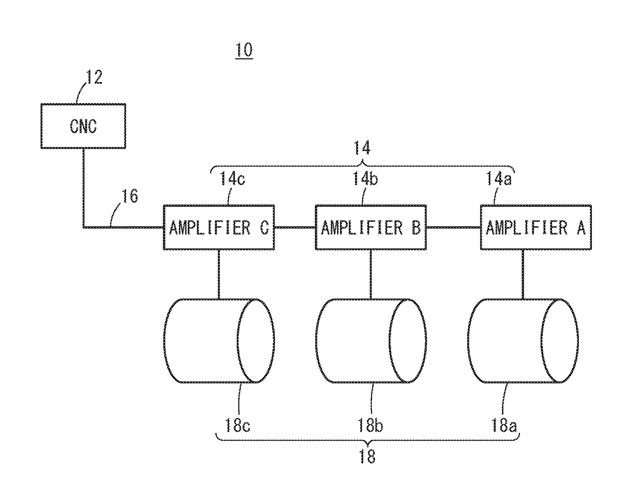
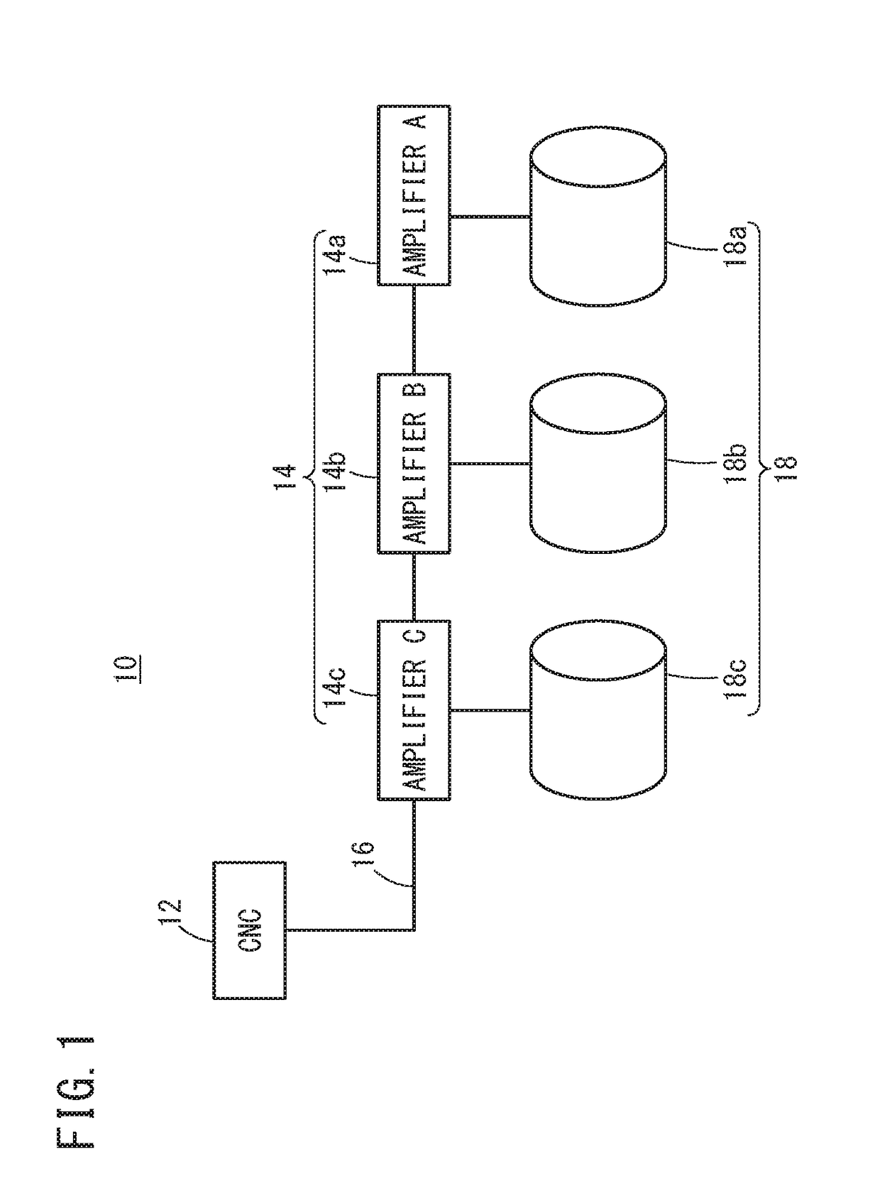
[0028]FIG. 1 is a diagram showing a configuration of a communications system 10 according to a first embodiment. The communications system 10 includes a computer numerical control device (hereinafter referred to as a CNC) (transmitting node) 12, an amplifier A 14a, an amplifier B 14b, and an amplifier C 14c. Hereinafter, unless distinguished specifically from each other, the amplifier A 14a, the amplifier B 14b, and the amplifier C 14c will be referred to collectively as amplifiers (receiving nodes) 14. The CNC 12, the amplifier A 14a, the amplifier B 14b, and the amplifier C 14c are connected in a daisy chain fashion by a serial communications circuit 16. The amplifiers 14 are connected to the serial communications circuit 16 in order of the amplifier A 14a, the amplifier B 14b, and the amplifier C 14c in a farthest ordering from the CNC 12, i.e., with the amplifier A 14a being farthest from the CNC 12.

[0029]The CNC 12 is a control device adapt...

second embodiment

[0048]FIG. 9 is a diagram showing the configuration of a communications system 10 according to a second embodiment. Similar to the communications system 10 according to the first embodiment, the communications system 10 includes a computer numerical control device (CNC) 12, an amplifier A 14a, an amplifier B 14b, and an amplifier C 14c. The CNC 12, the amplifier A 14a, the amplifier B 14b, and the amplifier C 14c are connected by the serial communications circuit 16. The amplifiers 14 are connected to the serial communications circuit 16 in order of the amplifier A 14a, the amplifier B 14b, and the amplifier C 14c in a farthest ordering from the CNC 12, i.e., with the amplifier A 14a being farthest from the CNC 12.

[0049]FIG. 10 is a time chart showing a transmission timing of packets transmitted from the CNC 12. In the communications system 10 according to the present embodiment, packets including motor command values and the like are transmitted from the CNC 12 to each of the ampli...

third embodiment

[0060]FIG. 13 is a diagram showing the configuration of a communications system 10 according to a third embodiment. Similar to the communications system 10 according to the first embodiment, the communications system 10 includes a computer numerical control device (CNC) 12, an amplifier A 14a, an amplifier B 14b, and an amplifier C 14c. The CNC 12, the amplifier A 14a, the amplifier B 14b, and the amplifier C 14c are connected by the serial communications circuit 16. The amplifiers 14 are connected to the serial communications circuit 16 in order of the amplifier A 14a, the amplifier B 14b, and the amplifier C 14c in a farthest ordering from the CNC 12, i.e., with the amplifier A 14a being farthest from the CNC 12.

[0061]FIG. 14 is a time chart showing a transmission timing of packets transmitted from the CNC 12. In the communications system 10 according to the present embodiment, packets including motor command values and the like are transmitted from the CNC 12 respectively to each...


PUM


Abstract

A communications system includes a computer numerical control device, which is hereinafter referred to as a CNC, and amplifiers connected to the CNC by a serial communications circuit, and in the communications system, packets are transmitted from the CNC to the amplifiers at each of predetermined periods. Each of the packets contains at least data and an error detection code. The CNC calculates an allowable number of transmissions at which the packets can be transmitted within the predetermined period, and transmits the same packet a plurality of times within the allowable number of transmissions. The amplifiers check the error detection codes of the received packets, and acquire data of the packets for which no errors are detected.

Description

CROSS-REFERENCE TO RELATED APPLICATION[0001]This application is based upon and claims the benefit of priority from Japanese Patent Application No. 2017-040310 filed on Mar. 3, 2017, the contents of which are incorporated herein by reference.BACKGROUND OF THE INVENTIONField of the Invention[0002]The present invention relates to a communications system and a communication method for a communications system.Description of the Related Art[0003]Japanese Laid-Open Patent Publication No. 08-116331 discloses that when a terminal device is incapable of normally receiving packets transmitted by a master device, the terminal device transmits a negative response to the master device, and when the negative response is received by the master device, the packets are retransmitted from the master device to the terminal device.SUMMARY OF THE INVENTION[0004]With the technique disclosed in Japanese Laid-Open Patent Publication No. 08-116331, since the master device (transmitting node) retransmits the ...

Claims


Application Information

Patent Timeline
IPC IPC(8): H04L1/00
CPCH04L1/0042H04L1/0061H04L1/08
Inventor KOMAKI, KUNITAKA
Owner FANUC CORP
Why Eureka
Try Eureka