
Learning driver rate of pedal change

a technology of driver rate and pedal change, applied in the direction of brake system, brake component, transportation and packaging, etc., can solve the problems of driver being forced to stop or accelerate, driver encountering many obstacles, driver may need to suddenly brake or accelerate,

Active Publication Date: 2018-09-13
TOYOTA MOTOR ENGINEERING & MANUFACTURING NORTH AMERICA
View PDF3 Cites 8 Cited by
  • Summary
  • Abstract
  • Description
  • Claims
  • Application Information

AI Technical Summary

Benefits of technology

The patent describes a system that predicts when a driver will brake or accelerate their vehicle, and causes the vehicle to react accordingly. This system uses sensors to detect the rate at which the driver presses the brakes or accelerates, and a computer program to predict when a braking or acceleration event will occur. The system can also use information from navigational maps to make the predictions. The technical effect of this system is to improve the safety and efficiency of vehicles by predicting and responding to braking or acceleration events, and improving driver behavior by providing real-time feedback.

Problems solved by technology

Drivers encounter many obstacles when navigating a vehicle to a destination.
As a result, a driver may need to suddenly brake or accelerate to avoid the obstacles.
As the vehicle approaches an obstacle, the driver may be required to stop or accelerate.
However, there is a lag between when the driver depresses the brake pedal or the accelerator pedal and when the brakes or accelerator are fully engaged.

Method used


Image

  • Learning driver rate of pedal change
  • Learning driver rate of pedal change
  • Learning driver rate of pedal change

Examples


Embodiment Construction

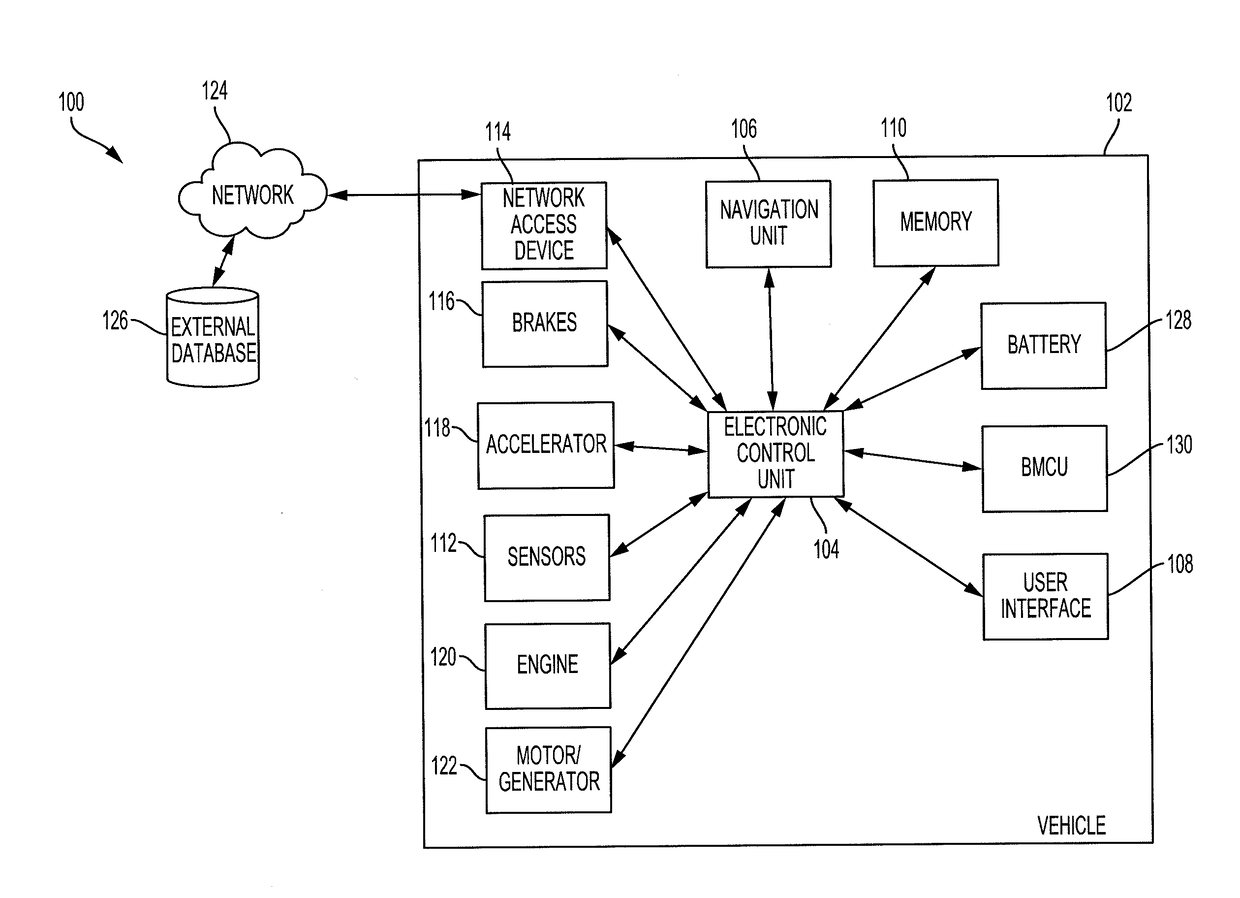
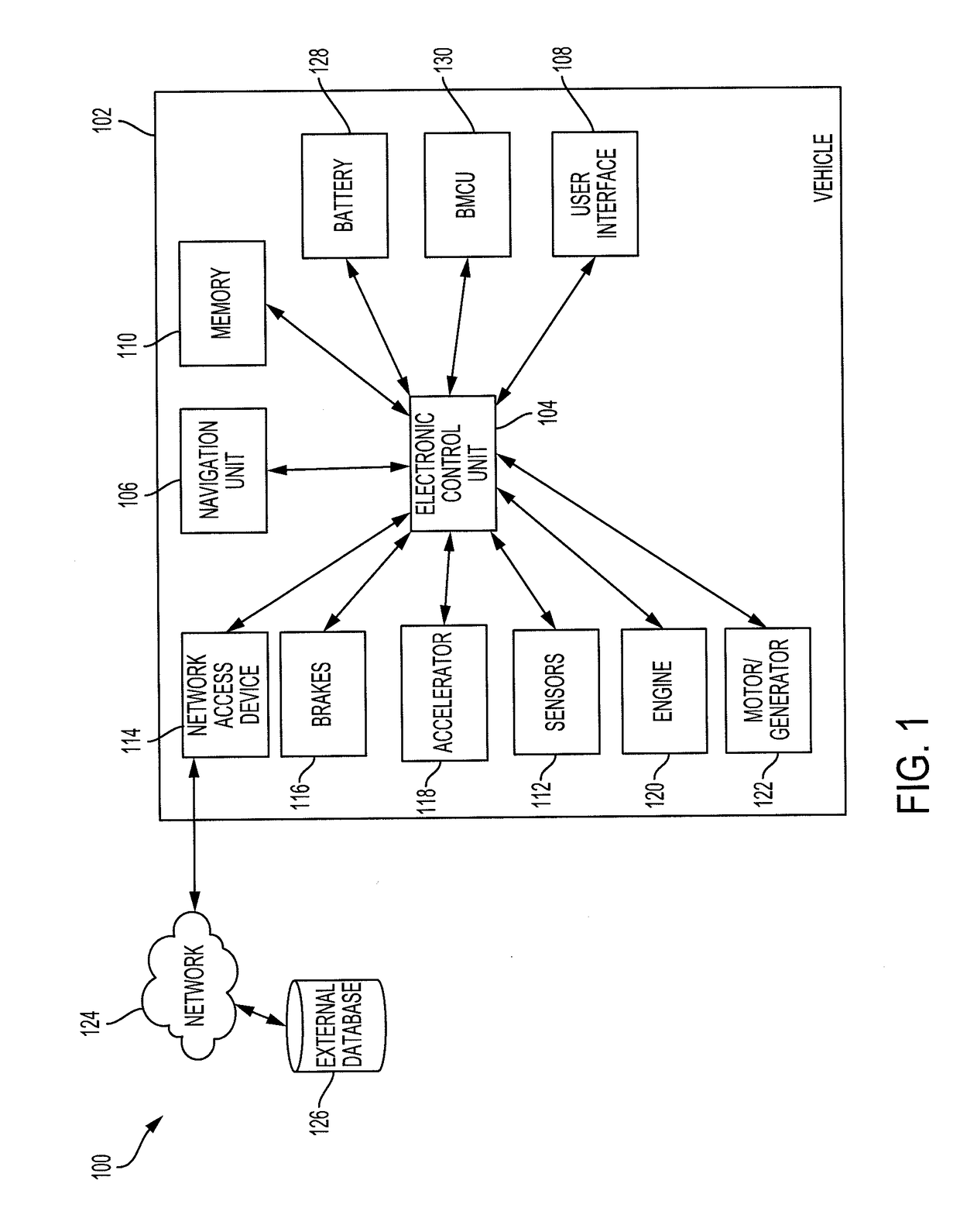
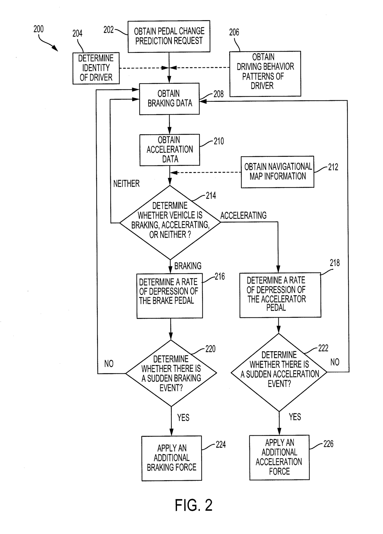
[0018]Disclosed herein are systems, vehicles and methods for controlling the brakes and accelerator to predict a driver's intention to change the position of the brakes and accelerator. Particular embodiments of the subject matter described in this specification may be implemented to realize one or more of the following advantages. A pedal change prediction system operates the brakes and / or the accelerator to reduce the response time to fully engage the brakes or the accelerator. The pedal change prediction system predicts when the driver intends to press either the accelerator pedal or the brake pedal all the way down. In response, the pedal change prediction system preemptively causes the associated action, such as fully engaging the throttle or brake. This facilitates a quicker implementation of a driver's intention.

[0019]Other benefits and advantages include adjusting the associated action based on the surrounding environment. By recognizing the surrounding environment, the peda...


PUM


Abstract

Methods, systems, and apparatus for predicting the braking or acceleration of a vehicle. The pedal change prediction system includes a braking sensor for providing braking data or an acceleration sensor pedal for providing acceleration data. The pedal change prediction system includes an electronic control unit that is configured to determine a rate of depression of the brake pedal or the acceleration pedal that is associated with a first braking force or a first acceleration force. The electronic control unit is configured to predict a triggering event that is either a braking event or an acceleration event. The electronic control unit predicts the triggering event based on the rate of depression of the brake pedal or the acceleration pedal and causes the vehicle to apply a second braking force or a second acceleration force.

Description

BACKGROUND1. Field[0001]This specification relates to a system and a method for predicting the braking or acceleration of a vehicle.2. Description of the Related Art[0002]Drivers encounter many obstacles when navigating a vehicle to a destination. As a result, a driver may need to suddenly brake or accelerate to avoid the obstacles. That is, the driver may need to more forcefully depress the brake or the accelerator to stop or accelerate the vehicle. The obstacle may be unexpected, such as a ball that rolls into the street, or may be expected, such as a stop sign or an on-ramp. As the vehicle approaches an obstacle, the driver may be required to stop or accelerate. For example, if a ball rolls into the path of the vehicle, the driver may need to suddenly stop by fully engaging the brakes.[0003]When a driver intends to suddenly stop or accelerate, the driver may rapidly depress the brake pedal or depress the accelerator pedal to stop or accelerate. However, there is a lag between whe...

Claims


Application Information

Patent Timeline
IPC IPC(8): B60W30/18B60T7/04B60K26/02B60T7/12B60W40/09B60W10/06B60W10/18
CPCB60W30/18109B60W2040/0809B60K26/021B60T7/12B60W40/09B60W10/06B60W10/18B60T2220/02B60T2220/04B60T2260/09B60T2220/06B60T2210/30B60W2540/12B60W2540/106B60W2540/28B60W2550/142B60W2550/12B60W2550/20B60T7/042B60W10/04B60W50/08B60W50/10B60W2540/00B60W2540/043B60W2540/10B60W2540/30B60W2556/50B60W2552/15B60W2554/00B60W2555/20
Inventor WESTOVER, NATHAN C.
Owner TOYOTA MOTOR ENGINEERING & MANUFACTURING NORTH AMERICA
Learn More