Laboratory ventilation integration

Active Publication Date: 2018-09-13
SIEMENS SWITZERLAND
View PDF12 Cites 9 Cited by
  • Summary
  • Abstract
  • Description
  • Claims
  • Application Information

AI Technical Summary

Benefits of technology

[0004]By way of introduction, the preferred embodiments described below include methods, systems, instructions, and computer readable media for laboratory ventilation integration. The HVAC room controller requests changes in the exhaust set point of one or more fume hoods. By allowing the fum

Problems solved by technology

This limits efforts

Method used


Image

  • Laboratory ventilation integration
  • Laboratory ventilation integration
  • Laboratory ventilation integration

Examples


Embodiment Construction

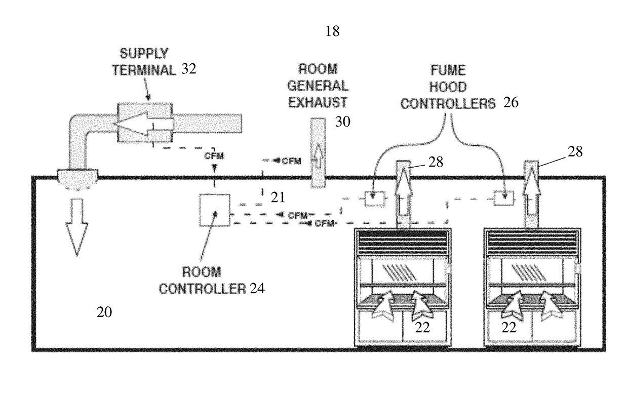
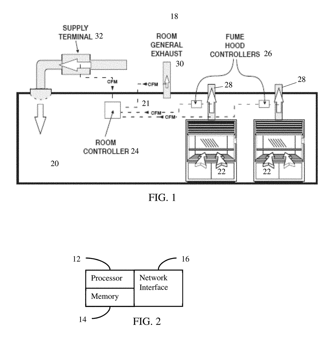
[0016]Lab room ventilation is enhanced by integration of local exhaust ventilation (e.g., from a hood) and room ventilation (e.g., from a general HVAC exhaust). The room controller may request a local exhaust ventilation device to increase exhaust flow. The controller for the local exhaust ventilation device receives the request and may increase exhaust flow in response. The local exhaust ventilation flow controller evaluates the request from the room controller. If the higher flow is possible and does not interfere with correct local exhaust ventilation operation, the local exhaust ventilation controller sets a higher flow rate. The local exhaust ventilation controller continues to communicate actual flow rate to the room controller. With increased local exhaust ventilation air flow, the room controller is free to increase supply flow for cooling or for room air replacement even where the room ventilation is at a maximum flow.

[0017]FIG. 1 shows an example embodiment of a laboratory...


PUM


Abstract

Laboratory ventilation is integrated. The HVAC room controller requests changes in the exhaust set point of one or more fume hoods. By allowing the fume hoods to respond to such HVAC requests, the fume hood exhaust may be turned down to a point below the highest level that could be needed. The request may be used to turn the fume hood exhaust back up, so greater energy savings may be possible in non-peak demand operation of the HVAC system.

Description

FIELD[0001]The present embodiments generally relate to ventilation in laboratories and, more particularly, to integrating different sources of ventilation.BACKGROUND[0002]A typical laboratory ventilation system includes general exhaust ventilation from the heating, ventilation, and air conditioning (HVAC) system and includes local exhaust ventilation from fume hoods. The fume hoods are provided for purposes other than HVAC, so are operated autonomously. The fume hoods set their flow rates independently of other consideration in the room. The fume hoods communicate their exhaust flow rates to the room controller for HVAC, but this integration is for the HVAC system to use to control the general exhaust ventilation based on total exhaust.[0003]Reduction in total exhaust allows for reduction in HVAC air supply, so energy may be conserved. The exhaust from fume hoods may be set to limit the total exhaust. However, reduction in the set point for the exhaust flow from hoods stops at the p...

Claims


Application Information

Patent Timeline
IPC IPC(8): F24F11/00B08B15/02F24F7/00
CPCF24F11/30B08B15/023F24F2007/001F24F11/0001F24F7/00B08B15/002F24F7/06F24F2011/0005
Inventor COOGAN, JAMES J.BLASK, MATTHIASKEMPF, GREGORY
Owner SIEMENS SWITZERLAND
Why Eureka
Try Eureka