
Microchannel heat exchanger

Active Publication Date: 2018-09-13
FUJITSU GENERAL LTD
View PDF3 Cites 3 Cited by
  • Summary
  • Abstract
  • Description
  • Claims
  • Application Information

AI Technical Summary

Benefits of technology

The invention makes it easier to join temperature sensors that measure the temperature of working fluids with the control board and lead wires.

Problems solved by technology

In this case, the sensing point of the temperature sensor is not in direct contact with the working fluid, and hence it is impossible to correctly measure the temperature of the working fluid.

Method used


Image

  • Microchannel heat exchanger
  • Microchannel heat exchanger
  • Microchannel heat exchanger

Examples


Embodiment Construction

[0046]Hereinafter, an embodiment of the present invention will be described with reference to the drawings.

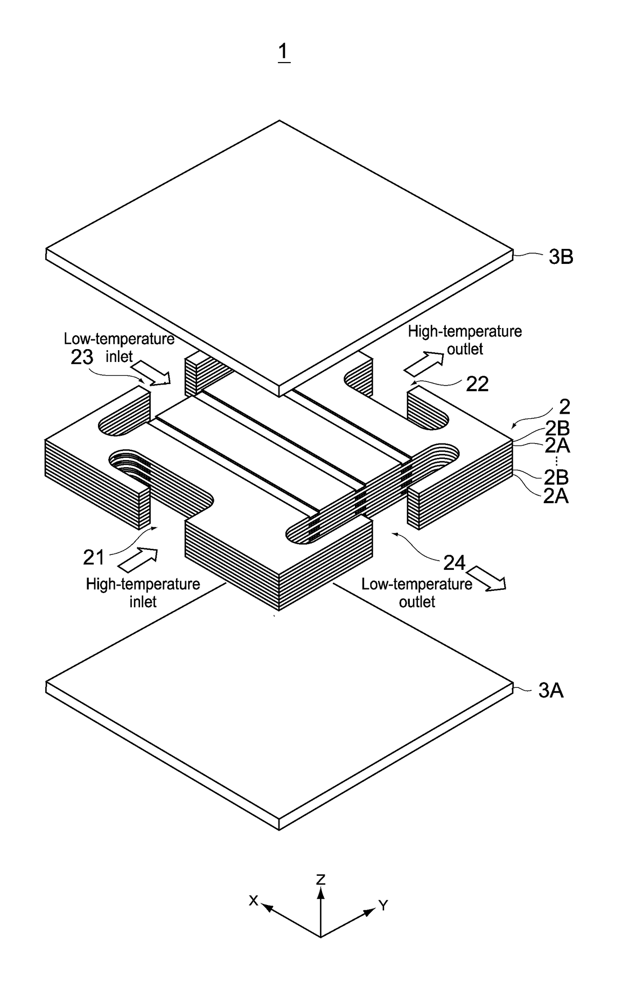
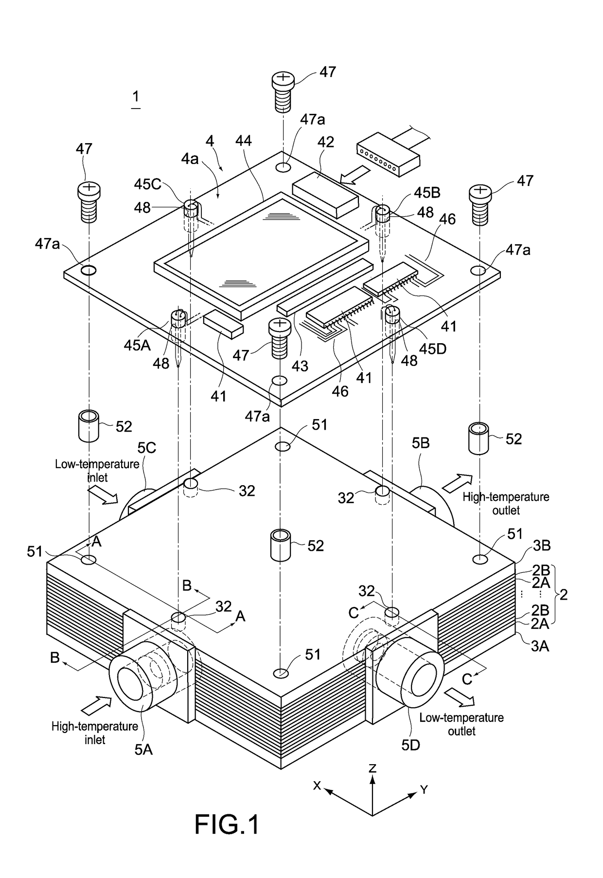
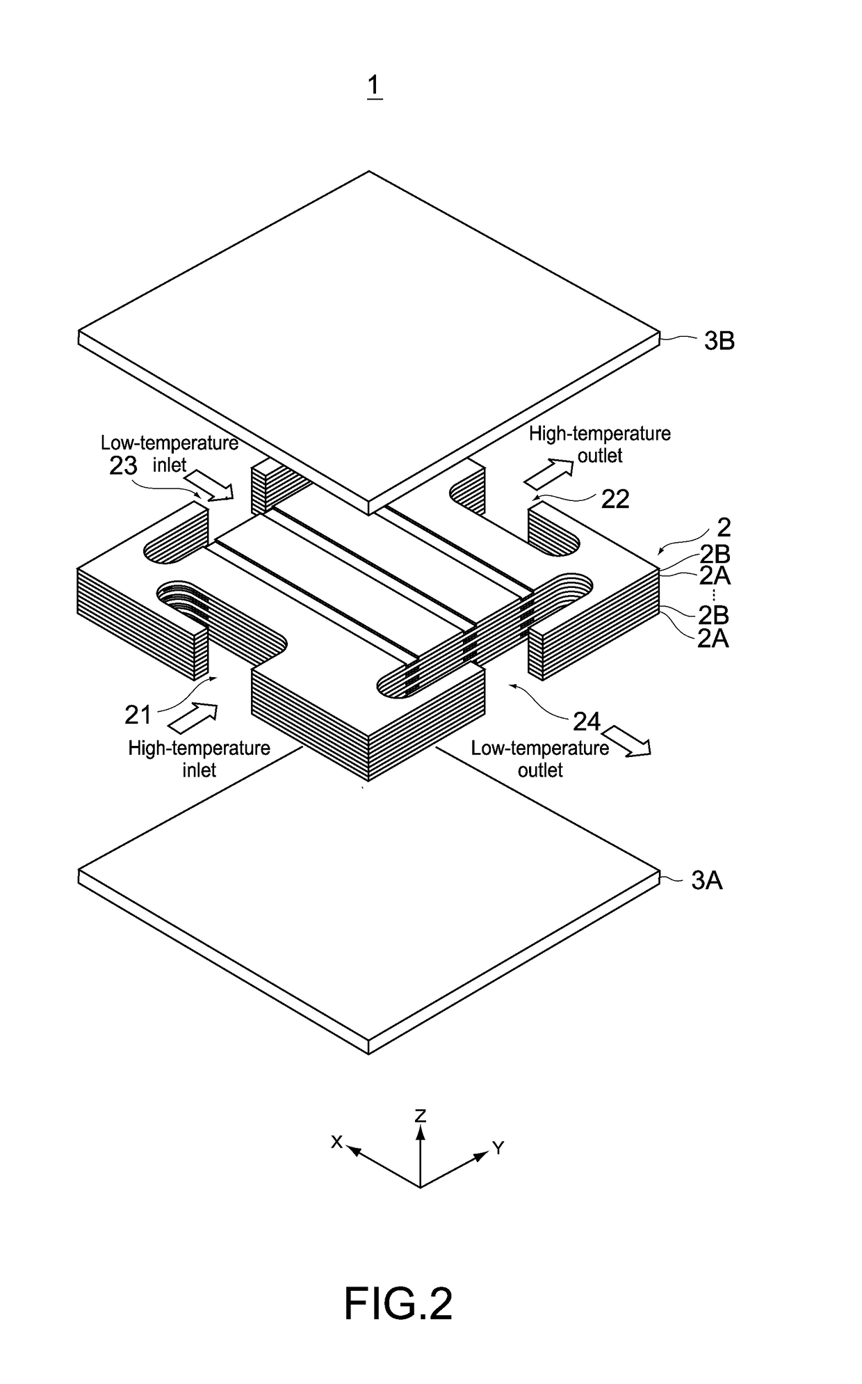
[0047]FIG. 1 is a perspective view showing a microchannel heat exchanger according to a first embodiment of the present invention with a printed board that is a control board being detached. FIG. 2 is a perspective view showing a heat exchanger body of the microchannel heat exchanger of FIG. 1 in a partially exploded state.

[0048][Entire Configuration]

[0049]As shown in those figures, this microchannel heat exchanger 1 includes a heat exchanger body 2 that is a stack of channel layers, a high-temperature-side outer case plate 3A, a low-temperature-side outer case plate 3B, a high-temperature inlet pipe 5A that allows a high-temperature fluid to flow in, a high-temperature outlet pipe 5B that allows the high-temperature fluid to flow out, a low-temperature inlet pipe 5C that allows a low-temperature fluid to flow in, a low-temperature outlet pipe 5D that allows the low-temperature...


PUM


Abstract

This microchannel heat exchanger includes: a heat exchanger body including a channel layer stack formed in such a manner that a plurality of high-temperature channel layers provided with a channel for a high-temperature fluid and a plurality of low-temperature channels layers provided with a channel for a low-temperature fluid are alternately stacked, an inlet and an outlet for the high-temperature fluid, and an inlet and an outlet for the low-temperature fluid; and a control board that is fixed in a stacking direction of the heat exchanger body, and that at least installs a plurality of temperature sensors that are inserted in the stacking method of the heat exchanger body in such a manner that a sensing point is arranged near each of the inlet and the outlet for the high-temperature fluid and the inlet and the outlet for the low-temperature fluid.

Description

TECHNICAL FIELD[0001]The present invention relates to a microchannel heat exchanger configured by stacking a plurality of heat transfer plates in which channels for a working fluid for heat exchange are formed.BACKGROUND ART[0002]A heat exchanger is used as one element of a refrigeration cycle. The heat exchanger is an essential part for changing a temperature of a working fluid in the refrigeration cycle to a desired temperature. Various heat exchangers exist. In particular, microchannel heat exchangers have excellent performance, which is becoming more and more known. The microchannel heat exchangers are being developed for practical application.[0003]Those microchannel heat exchangers include a stacked microchannel heat exchanger. This stacked microchannel heat exchanger is configured as follows, for example. A stack is formed by alternately stacking heat transfer plates having surfaces in which minute high-temperature channels are formed and heat transfer plates having surfaces ...

Claims


Application Information

Patent Timeline
IPC IPC(8): F28F27/00F28D9/00F28F3/08G01K1/02G01K1/14
CPCF28F27/00F28D9/0037F28F3/086G01K1/024G01K1/14F28F2260/02F28D9/0062F28D2021/0029F28F3/04F28F9/0263F28F9/028F28F9/0282F28F13/08F28F13/12F25B49/02G01K13/02
Inventor WANG, KAIJIAN
Owner FUJITSU GENERAL LTD
Learn More