Plate, and holding apparatus and holding method for the plate

Active Publication Date: 2020-02-06
KROSAKI HARIMA CORP
View PDF0 Cites 0 Cited by
  • Summary
  • Abstract
  • Description
  • Claims
  • Application Information

AI Technical Summary

Benefits of technology

[0034]According to a plate-holding apparatus and a holding method for a plate of the present invention, gaps are ensured such that, when the plate is held by engaging the to-be-held portion of the plate with the engagement groove of a holding portion of the plate-holding apparatus, the to-be-held portion of the plate is movable in a longitudinal direction, a width direction, and a thickness direction of the plate, and thereby the plate can move in any direction within the range of the gap. Th

Problems solved by technology

When this plate is damaged and has expired a usable life thereof, it is necessary to open the sliding nozzle device, extract the old plate from each plate-receiving metal frame, and replace it with a new plate.
This replacement operation must be performed under high temperatures, and the weight of the plate is about 30 kg for heavy plates, which is a heavy burden on an operator.
However, simply grasping the plate makes it difficult to accurately control the positioning of the plate with respect to the plate-receiving metal frame.
However, in the case of

Method used


Image

  • Plate, and holding apparatus and holding method for the plate
  • Plate, and holding apparatus and holding method for the plate
  • Plate, and holding apparatus and holding method for the plate

Examples


Example

First Embodiment

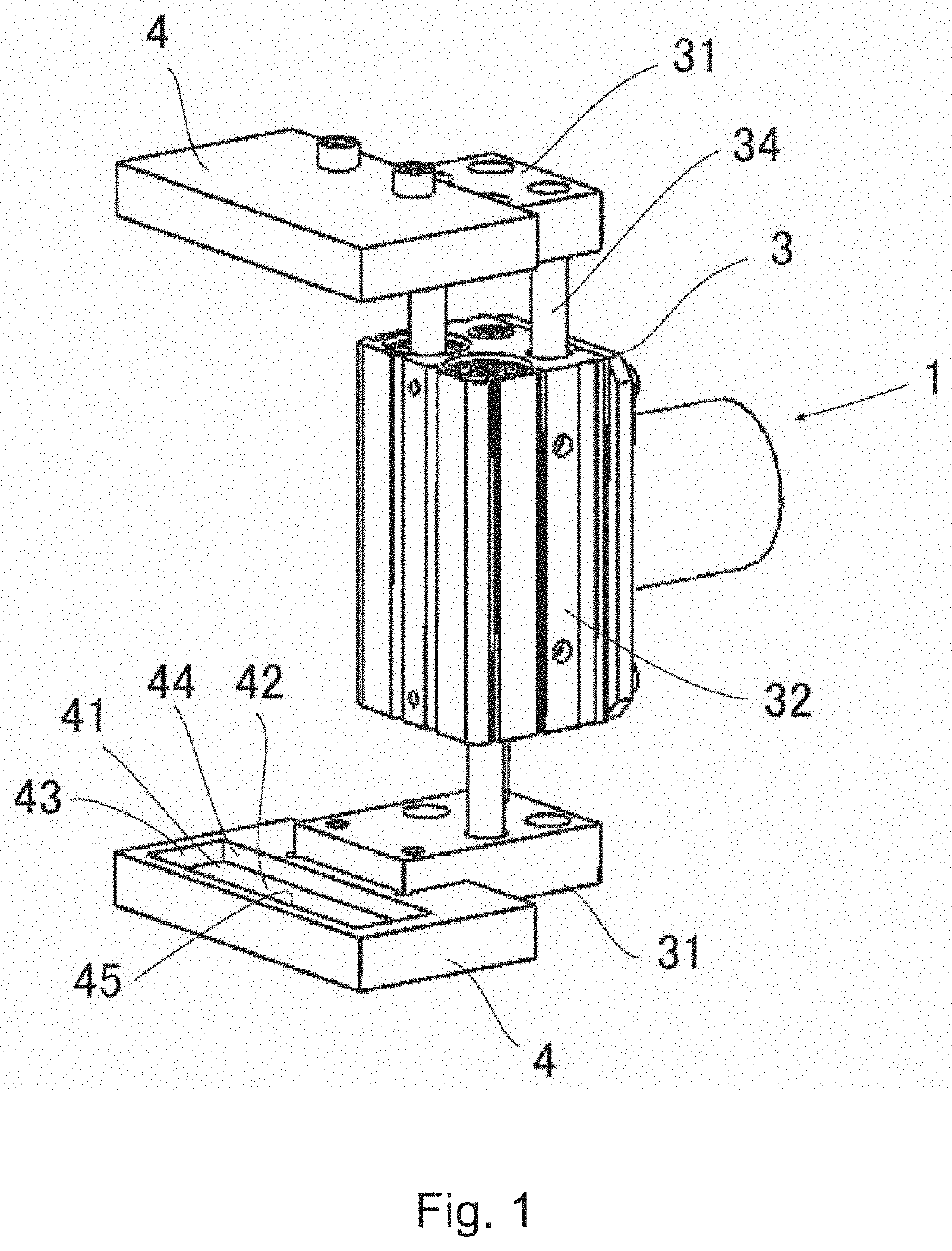
[0047]FIG. 1 illustrates a plate-holding apparatus according to a first embodiment of the present invention. The plate-holding apparatus 1 comprises a parallel hand 3 serving as a widening and narrowing means, and a pair of (two) holding portions 4 each attached to a respective one of a pair of (two) parallel claws 31 of the parallel hand 3. This parallel hand 3 is configured such that a rod 34 is extended and retracted with respect to a body 32 thereof to widen and narrow a distance between the pair of parallel claws 31. Further, each of the holding portion 4 has an engagement groove 41 at a distal end portion thereof. The pair of holding portions 4 are arranged in opposed and parallel relation to each other, and can be synchronously moved by the parallel hand 3 such that they come close to and away from each other. Specifically, the parallel hand 3 is configured such that the distance between the pair of holding portions 4 is widened and narrowed while the parallel...

Example

Second Embodiment

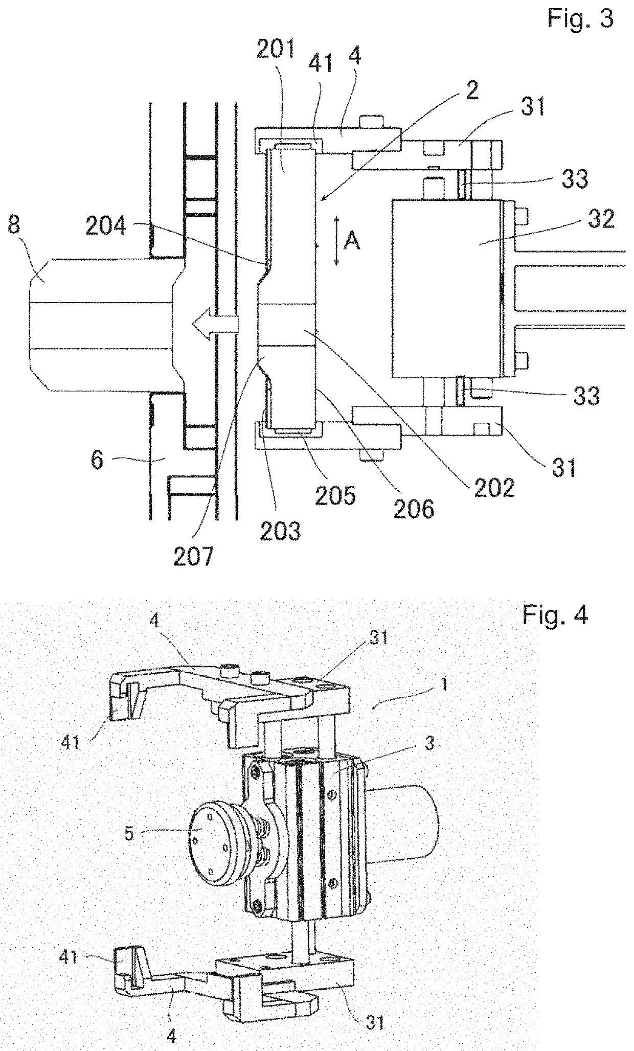
[0055]FIG. 4 illustrates a plate-holding apparatus according to a second embodiment of the present invention. In addition to a parallel hand 3 as widening and narrowing means and a pair of (two) holding portions 4 attached to a pair of parallel claws 31 of the parallel hand 3, this plate-holding apparatus 1 comprises a pressing portion 5 provided on the body 32 on the holding portion 4 side between the parallel claws 31. Further, each of the holding portions 4 is substantially U-shaped in a plan view, and has two engagement grooves 41 at the distal end portions of opposite ends of each of the holding portions.

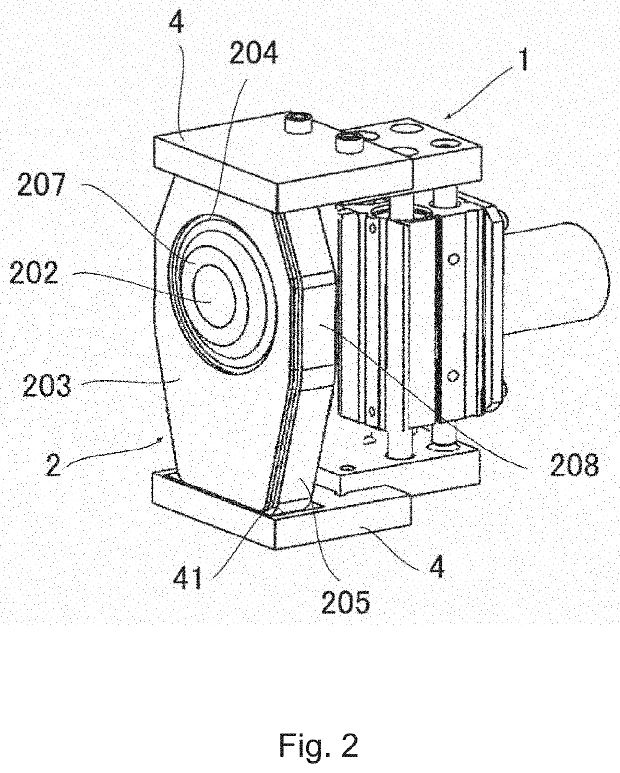
[0056]As shown in FIGS. 5 and 6, the plate 2 held by the plate-holding apparatus 1 is provided with a metal backplate 203 on the back side thereof, a side surface covered with the metal band 205 and plate-shaped fixing portions 209 extending in the longitudinal direction from the backplate 203. These features are the same as the plate disclosed in Patent Docume...

Example

Third Embodiment

[0069]In a third embodiment, although the same plate-holding apparatus 1 as that of the second embodiment is used, the shape of the plate, specifically the position of the engagement protrusion 210 is different from that of the second embodiment. Specifically, in this embodiment, engagement protrusion 210 is provided in the longitudinal opposite ends of the backplate 203 by a total number of four, and among the four engagement protrusions, each of two pair of two engagement protrusions are provided, respectively, in opposite ends of each of the backplate 203. As in the second embodiment, the engagement protrusion 210 of the third embodiment also has plate-shape extending from the backplate 203 and is provided symmetrically with respect to the longitudinal central axis of the plate. The engagement protrusion 210 also has a corner portion orthogonal to the longitudinal central axis of the plate on the side opposite to a nozzle hole of the plate.

DESCRIPTION OF REFERENCE...


PUM

PropertyMeasurementUnit
Thicknessaaaaaaaaaa
Widthaaaaaaaaaa
Distanceaaaaaaaaaa

Abstract

A plate, a plate-holding apparatus, and a holding method for the plate for facilitating work to attach the plate to a plate-receiving metal frame of a sliding nozzle device. A gap is ensured between a to-be-held portion of the plate and an inner wall surface of an engagement groove such that, when the plate is held by engaging the to-be-held portion of the plate with the engagement groove of a holding portion of the plate-holding apparatus, the plate is movable in the longitudinal direction, the width direction, and the thickness direction of the plate.

Description

TECHNICAL FIELD[0001]The present invention relates to a plate for use in a sliding nozzle device for flow rate control of molten metal, a plate-holding apparatus for holding the plate, and a holding method for the plate.BACKGROUND ART[0002]The sliding nozzle device comprises two or three plates each made of a refractory material and attached to a plate-receiving metal frame. When this plate is damaged and has expired a usable life thereof, it is necessary to open the sliding nozzle device, extract the old plate from each plate-receiving metal frame, and replace it with a new plate. This replacement operation must be performed under high temperatures, and the weight of the plate is about 30 kg for heavy plates, which is a heavy burden on an operator.[0003]For this reason, a plate-holding apparatus for replacing the plate has been heretofore developed. For example, the following Patent Document 1 (JP H07-132484 A) discloses that a plate is grasped by a pair of claws of a parallel chuc...

Claims


Application Information

Patent Timeline
IPC IPC(8): B22D11/10B22D11/18
CPCB22D41/38B22D11/18B22D41/56B22D41/34B22D11/10B22D41/40B22D41/30B22D41/28B25J15/0253
Inventor IMAHASE, TOSHIHIRO
Owner KROSAKI HARIMA CORP
Why Eureka
Try Eureka